TEA6845AH Ver la hoja de datos (PDF) - Philips Electronics
Número de pieza
componentes Descripción
Lista de partido
TEA6845AH Datasheet PDF : 48 Pages
| |||
Philips Semiconductors
New In Car Entertainment (NICE) car radio
Product specification
TEA6845AH; TEA6845H
SYMBOL
PARAMETER
CONDITIONS
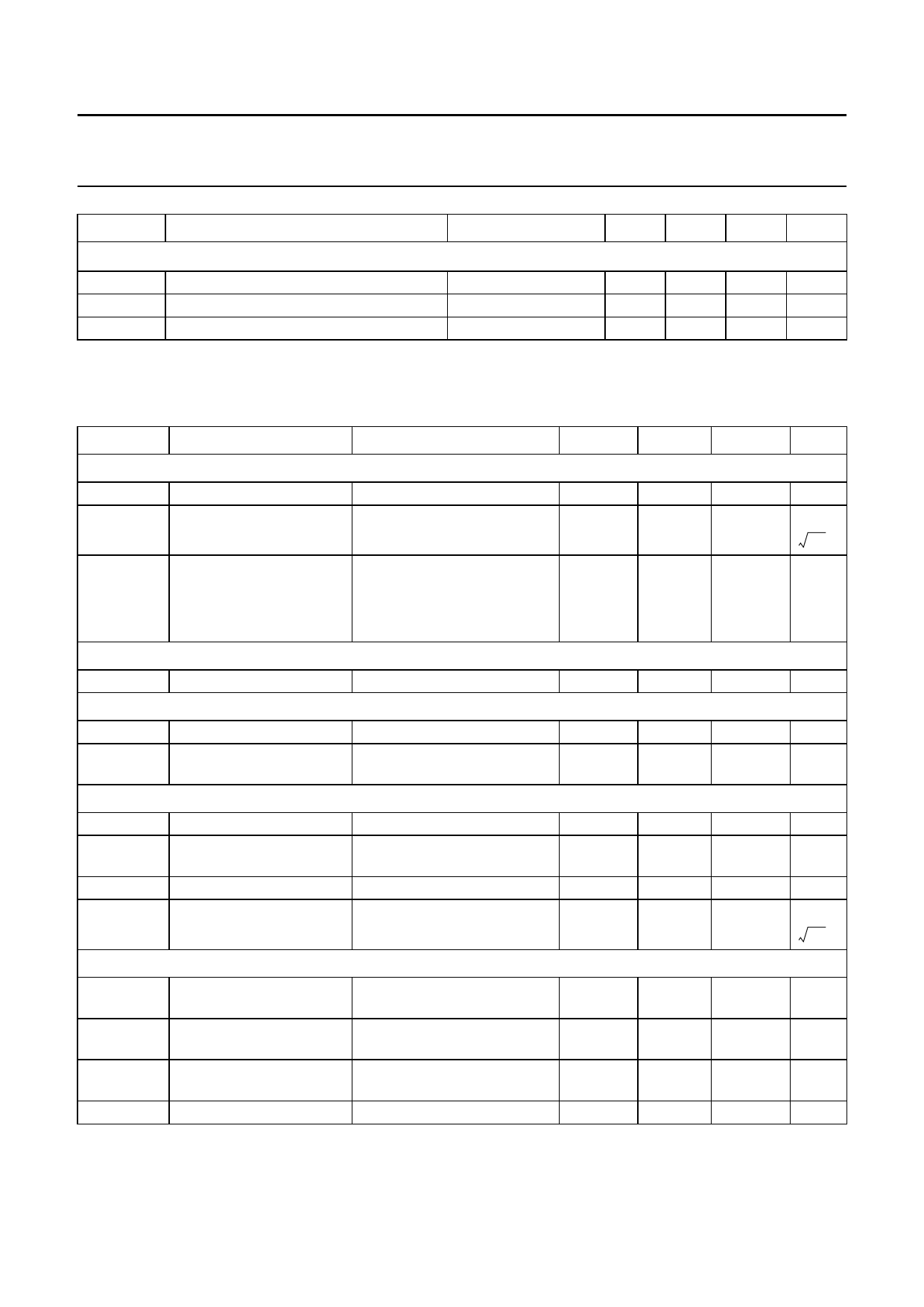
On-chip power supply reference current generator: pin Iref
Vo(ref)
Ro
Io(max)
output reference voltage
output resistance
maximum output current
MIN. TYP. MAX. UNIT
4
4.25
8
11
−100 −
4.5
V
13
kΩ
+100 nA
11 AC CHARACTERISTICS
VDDA1 = VDDA3 = VDDA4 = VDDA5 = VDDA6 = 8.5 V; VDDA2 = 5 V; VDDD = 5 V; Tamb = 25 °C; see Figs 9 and 10; unless
otherwise specified.
SYMBOL
PARAMETER
CONDITIONS
MIN.
TYP.
MAX. UNIT
Voltage controlled oscillator
fosc
oscillator frequency
C/N
carrier-to-noise ratio
151.2
−
fosc = 200 MHz; ∆f = 10 kHz −
101
248.2
−
MHz
-d----B----c--
Hz
RR
ripple rejection
fripple = 100 Hz;
VDDA3(ripple) = 100 mV (RMS)
fosc = 250 MHz
−
97
−
dB
fosc = 200 MHz
−
99
−
dB
FEEDBACK INPUT: PIN OSCFDB
Vi(bias)
input bias voltage
2.2
2.8
3.4
V
TANK CIRCUIT OUTPUT: PIN OSCTNK
VO
Vo(rms)
DC output voltage
AC output voltage
(RMS value)
fosc = 200 MHz
5
6.1
7.2
V
−
1.5
−
V
Crystal oscillator
fxtal
crystal frequency
Rxtal
crystal motional
resistance
Cxtal
crystal shunt capacitance
C/N
carrier-to-noise ratio
start of operating
fxtal = 20.5 MHz (10.25 MHz);
∆f = 10 kHz
20.4996
−
−
−
20.5
−
−
112
20.5004 MHz
500
Ω
18
pF
−
-d----B----c--
Hz
CIRCUIT INPUTS: PINS XTAL1, XTAL2 AND XTALGND
Vxtal(rms)
crystal voltage
(RMS value)
note 2
−
350
−
mV
VXTAL1,
VXTAL2
Ri
DC bias voltage
real part of input
impedance
1.7
2.1
2.5
V
VXTAL1 − VXTAL2 = 1 mV;
−500
−
−
Ω
note 1
Ci
input capacitance
note 1
8
10
12
pF
2001 Apr 12
12
Share Link: 