BD6583MUV-A Ver la hoja de datos (PDF) - ROHM Semiconductor
Número de pieza
componentes Descripción
Lista de partido
BD6583MUV-A
ROHM Semiconductor

BD6583MUV-A Datasheet PDF : 27 Pages
| |||
BD6583MUV-A
Technical Note
●How to select the number of LED lines of the current driver
When the number of LED lines of the current driver is reduced, the un-select can be set the matter that the unnecessary
LED1 ~ 6 terminal is connected to GND. When it uses with 4 lines and so on, it can correspond to it by connecting 2
unnecessary lines to GND.
RSTB is used as a power supply of this decision circuit. The select of the terminal is judged, It has no relation to the logic of
PWMPOW and PWMDRV and it isn't judged an unnecessary LED line even if it is connected to GND when it is judged a
necessary terminal once. This information can be reset by setting RSTB at 0V.
●Start control and select LED current driver
BD6583MUV-A can control the IC system by RSTB, and IC can power off compulsory by setting 0.2V or below. Also, It
powers on PWMPOW is at more than 1.4V and RSTB is at more than 2.25V.
When RSTB=PWMPOW=H, ISETH current is selected at PWMDRV=H and ISETL current is selected at PWMDRV=L.
The starting current in PWMDRV=L sets OFF second time rise of PWMDRV and it becomes 0mA setting after that.
After RSTB sets L once, the starting current can be flowed again by changing it to H.
RSTB
H
H
H
H
L
PWMPOW
L
H
L
H
L, H
PWMDRV
L
L
H
H
L, H
IC
LED current
Off OFF
On Starting current decided with ISETL
Off OFF
On Current decided with ISETH
Off OFF
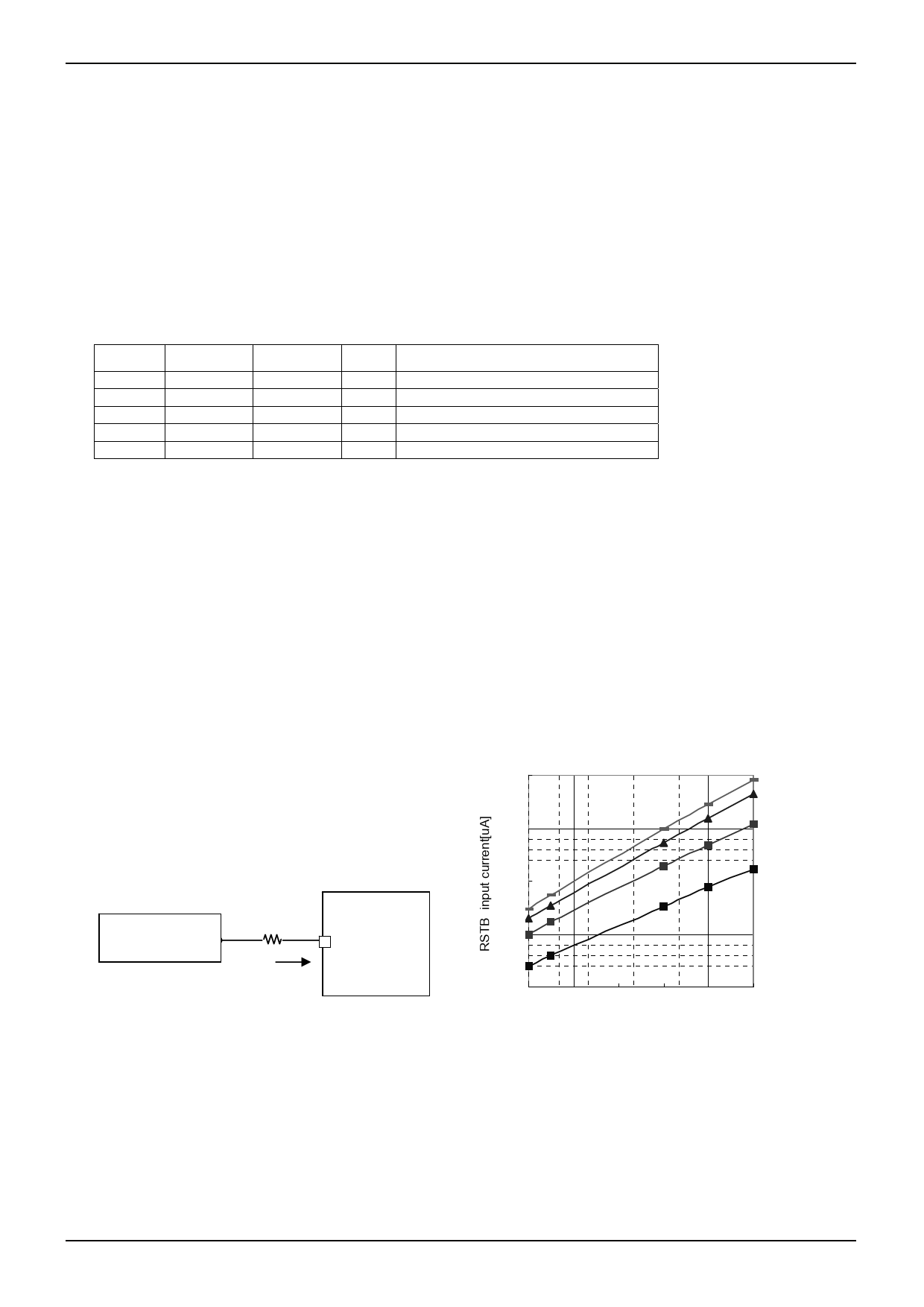
●Attendance point of the restriction resistance input to RSTB
When the restriction resistance is input to RSTB, it is necessary to consider the input current of RSTB.
The input current of RSTB changes that depending on the power-supply voltage and the temperature reference to Fig.33.
Because the temperature characteristic of the input current is shown in Fig.33, please choose resistance for which the
voltage of the terminal can be guaranteed to 2.1V or more.
And, it has the margin in the decision of resistance, and please confirm and make sure it is no problem in a real application.
The decision example of restriction resistance
1.When use the current driver of 6 parallel
2.9V(to RSTB power-supply) - restriction resistance value × 124μA(100 ℃ input current) > 2.1V
restriction resistance value < (2.9-2.1)/124μA=6.45kΩ
2.When use the current driver of 3 parallel
2.9V(to RSTB power-supply) - restriction resistance value × 430μA(100 ℃ input current) > 2.1V
restriction resistance value < (2.9-2.1)/430μA=1.86kΩ
BD6583MUV-A
Power supply Limit resistor
for RSTB
RSTB inflow current
RSTB
terminal
Fig .33
250
+100 ℃
+80 ℃
200
+25 ℃
150
-30 ℃
100
50
2.1 2.4 2.7
3
3.3 3.6
RSTB[V]
Fig .34 RSTB terminal voltage-RSTB inflow current
(At the time of the current driver 6 lines use)
www.rohm.com
© 2011 ROHM Co., Ltd. All rights reserved.
11/26
2011.06 - Rev.C
Share Link: