TQ5631 Ver la hoja de datos (PDF) - TriQuint Semiconductor
Número de pieza
componentes Descripción
Lista de partido
TQ5631 Datasheet PDF : 14 Pages
| |||
and IIP3 as well) of the downconverter alone, realizing that it
depends somewhat upon the type of image filter used and the
delay between it and the mixer? The most pragmatic approach
measures the NF, CG, and IIP3 with the filter in place. The
downconverter to filter distance(in pS) is set to be similar to that
which would be used in the end application. Then filter I.L. is
simply subtracted off of the system noise figure in order to arrive
at the downconverter NF. Similarly, the filter I.L. is subtracted
off of the IIP3 and added to the CG in order to arrive at those
numbers.
Use correct RF input power levels for accurate
test results
Because the CDMA devices have a number of gain states, it
important to make sure that IP3 measurements are not taken in
a state of compression. Additionally, using too low of a power
puts the IMD products too close to the noise floor for accurate
results.
Figure 7 shows the automated test setup that is used for
evaluation. Table 2 lists the RF input powers that we are using
to evaluate the devices, which has proved to be effective for
automated measurement. For bench measurement, it is
possible to use much lower input powers, since no hardware
routines are needed for peak searching.
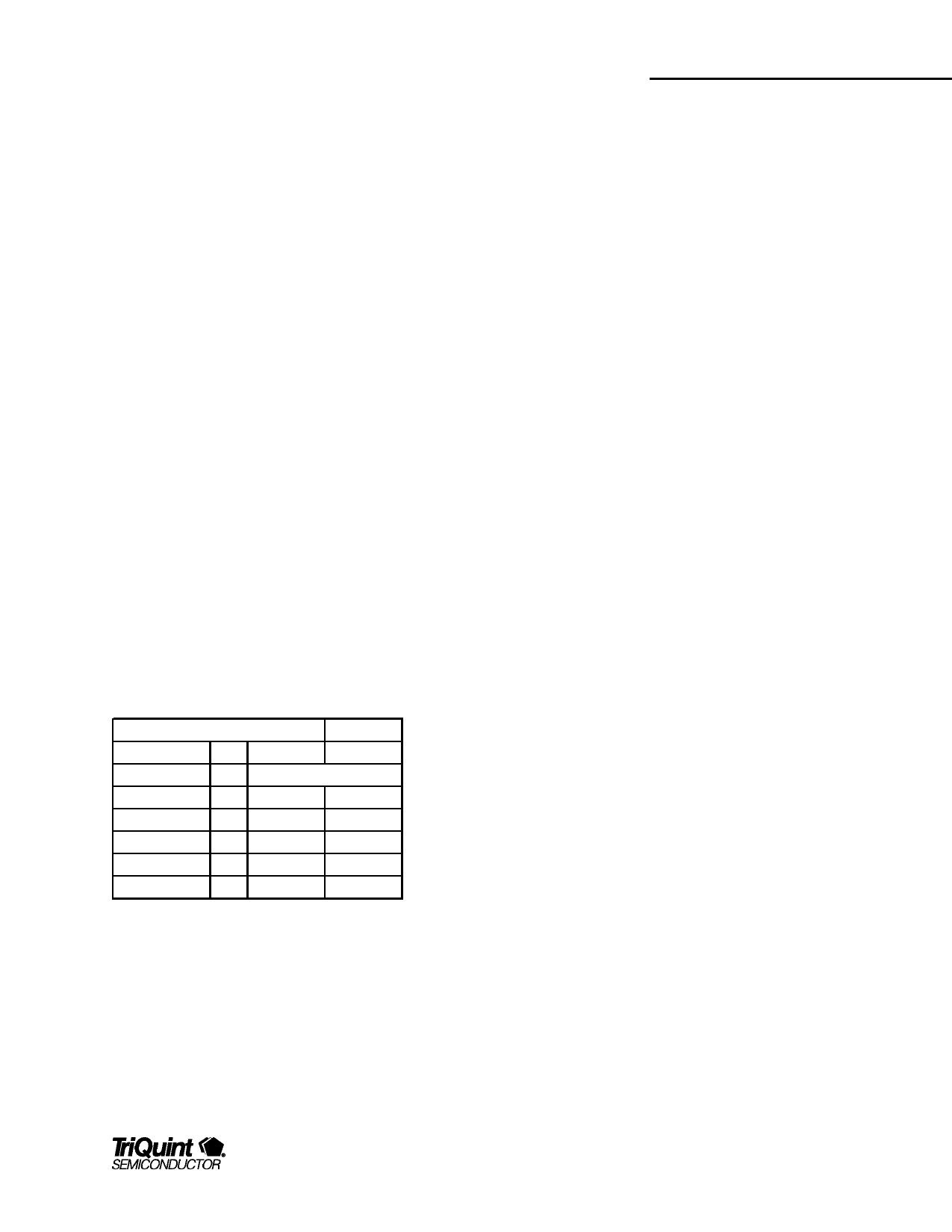
RF Input Power (dBm)
Mode
CDMA HGLL
CDMA HG
CDMA MG
CDMA LG
Downconverter
plus Filter
-20
-20
-5
-10
Table 2 Suggested RF Input Test Levels
TQ5631
Data Sheet
For additional information and latest specifications, see our website: www.triquint.com
11
Share Link: 