IRF240 Ver la hoja de datos (PDF) - New Jersey Semiconductor
Número de pieza
componentes Descripción
Lista de partido
IRF240 Datasheet PDF : 2 Pages
| |||
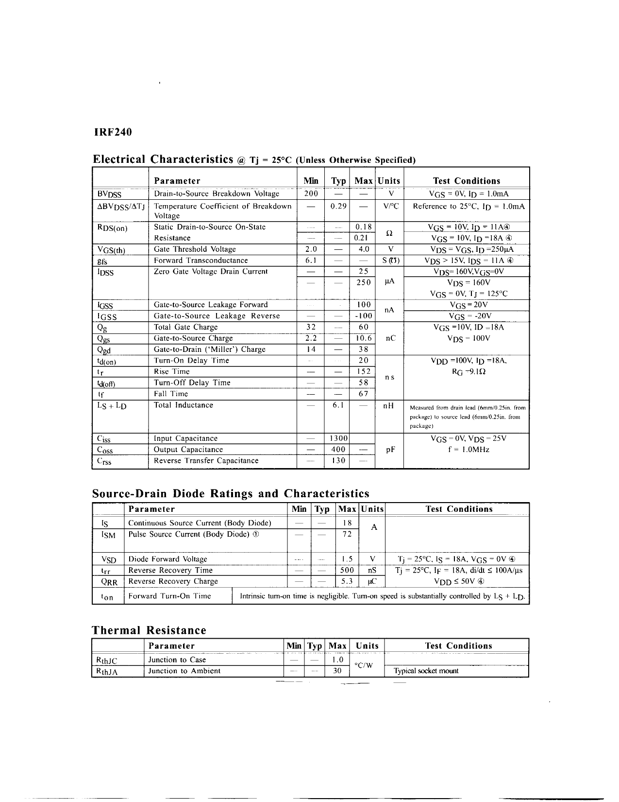
IRF240
Electrical Characteristics @ Tj = 25°C (Unless Otherwise Specified)
Parameter
Min Typ Max Units
Test Conditions
BVDSS
Drain-to-Source Breakdown Voltage
200 — — V
VGS = ov, ID = i.omA
ABVDSS/ATj Temperature Coefficient of Breakdown — 0.29 — v/°c Reference to 25°C, ID = I.OmA
Voltage
RDS(on)
VGS(th)
Sfs
IDSS
Static Drain-to-Source On-State
Resistance
Gate Threshold Voltage
Forward Transconductance
Zero Gate Voltage Drain Current
—
0.18
— 0.21
ij
2.0 — 4.0 V
6.1 — — s<n>
— — 25
— — 250 UA
VGS = iov, ID- nA®
VGS = iov, ID -ISA®
VDS = VGS, ID =250uA
VDS> isv, IDS = H A ®
VDS= i6ov,vos=ov
VDS = leov
'GSS
IGSS
Qg
Qgs
Qgd
td(on)
tr
kKoft)
tf
LS + LD
Gate-to-Source Leakage Forward
Gate-to-Source Leakage Reverse
Total Gate Charge
Gate-to-Source Charge
Gate-to-Drain ('Miller') Charge
Turn-On Delay Time
Rise Time
Turn-Off Delay Time
Fall Time
Total Inductance
100 nA
— — -100
VGS = OV, T j = 125°C
VGS = 2ov
VGS = -2ov
32 — 60
VGS=]OV, ID=I8A
2.2 — 10.6 nC
VDS= ioov
14 — 38
20
VDD =ioov, ID = ISA,
— — 152
—
— 58 n s
RG-9.1U
— — 67
6.1
nH
Measured from drain lead (6mm/0.25in. from
package) lo source lead (6mm/0.25in. from
package)
Ciss
Coss
Crss
Input Capacitance
Output Capacitance
Reverse Transfer Capacitance
— 1300
— 400 — pF
— 130 —
VGS = ov, VDS = 25V
f = I.OMHz
Source-Drain Diode Ratings and Characteristics
Parameter
is
Continuous Source Current (Body Diode)
ISM Pulse Source Current (Body Diode) ®
Min Typ Max Units
— — 18 A
72
Test Conditions
VSD Diode Forward Voltage
trr Reverse Recovery Time
QRR Reverse Recovery Charge
ton Forward Turn-On Time
.....
1.5 V
— — 500 nS
— — 5.3 uC
Tj = 25°C, Is = ISA, VGS = OV ®
Tj = 25°C, IF = ISA, di/dt < lOOA/us
VDD ^ 5ov ®
Intrinsic turn-on time is negligible. Turn-on speed is substantially controlled by LS + LD.
Thermal Resistance
Parameter
RthJC
RthJA
Junction to Case
Junction to Ambient
Min Typ Max Units
— — 1.0
—
30 "C/W
Test Conditions
Typical socket mount
Share Link: 