HMP8112A Ver la hoja de datos (PDF) - Harris Semiconductor
Número de pieza
componentes Descripción
Lista de partido
HMP8112A Datasheet PDF : 40 Pages
| |||
HMP8112A
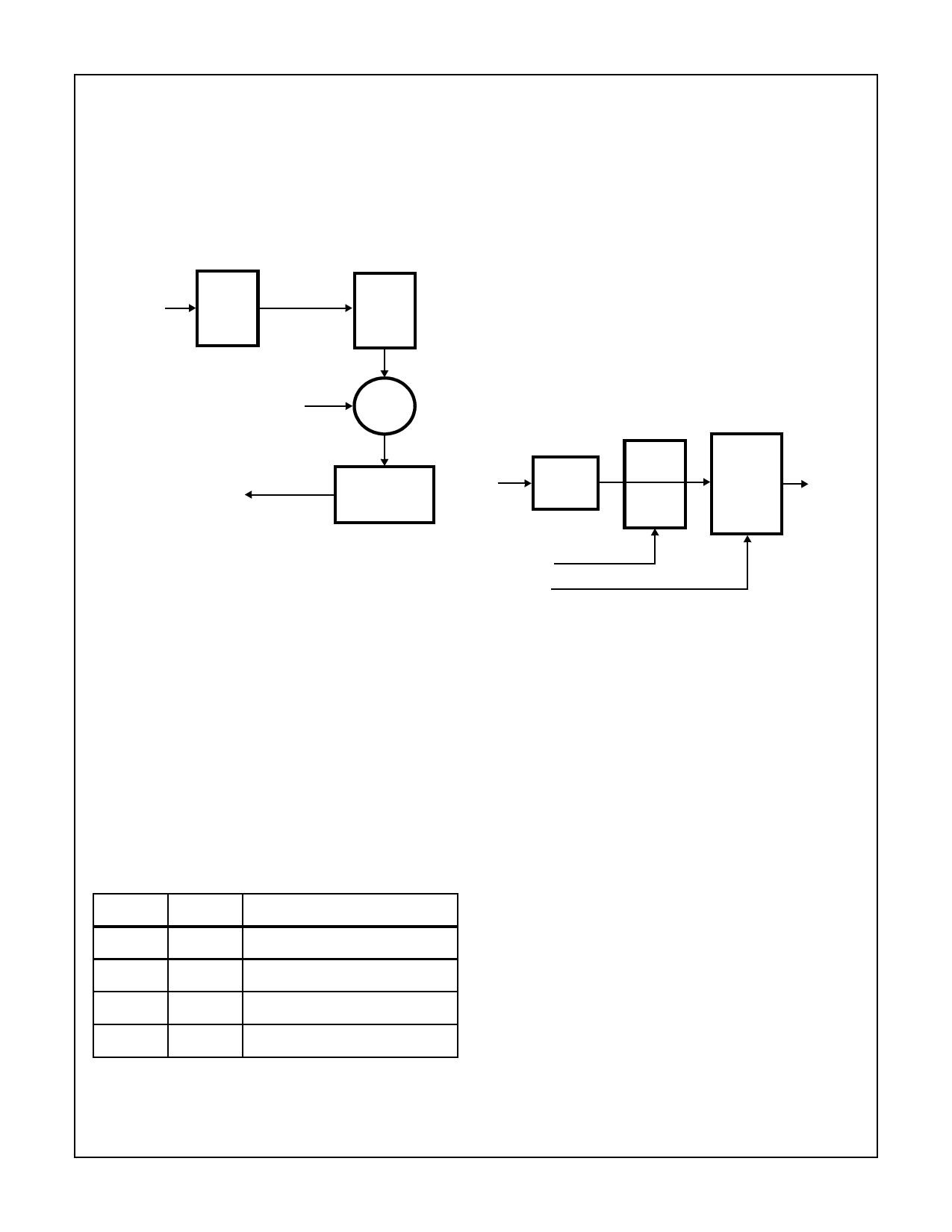
Hue or Tint Adjust
The Hue adjustment is applied to the U and the V color dif-
ference signal. The Hue adjusts the phase of the given UV
data. The Hue can be adjusted by ±30 degrees in 1/4 degree
increments. This is achieved by changing the Burst Phase
Locked reference point. Figure 11 shows the block diagram
for the color adjustment section. This default value for this
register is 0.
VIDEO
DATA
DEMODULATED
COLOR
UV DATA
DECODER
CHROMA
AGC AND
USER
SETTINGS
HUE OFFSET
UV DATA
+
HUE
ADJUST
The Color Killer
(AGC Hysteresis and Loop Limits)
The color killer will disable the color difference path and set
the U and V components to zero. The automatic color killer
circuitry uses the AGC threshold to determine the maximum
and minimum gain factor limits. The loop filter determines
how much the AGC gain factor can be changed within one
line. The maximum gain factor (Max = 8) and the minimum
gain factor (Min = 0.5) will limit the range of the AGC. When
the gain factor exceeds the maximum gain factor of 8, the
gain factor is limited to 8. Once the signal has an amplitude
of 1/16th, the nominal video the color killer is enabled and
the chroma phase locked loop holds it’s last phase refer-
ence. While the color killer is enabled, the U and V compo-
nents are forced to zero. Once the input video signal reaches
1/7th the optimum amplitude the color killer is disabled and
the color is returned.
TO INPUT SAMPLE
RATE
CONVERTER
CHROMA
PHASE LOCKED
LOOP
FIGURE 11. HUE ADJUST BLOCK DIAGRAM
Horizontal/Vertical Sharpness
The frequency characteristics of the video waveform can be
altered to enhance the sharpness of the picture. The Hori-
zontal Sharpness register acts as a 4 band equalizer where
the amplitude of specific frequency ranges can be
enhanced or diminished. The Sharpness Control Register
allows the Low (LF), Mid (MF) and High Frequency (HF)
bands of the luminance signal to be enhanced. Vertical
Sharpness can be adjusted to 1 or a factor of 0. The
RESET default is a factor of 1.0
The 2-bit values allow 4 choices of scaling factors. The
sharpness control helps to compensate for losses in the
scaling interpolators that can reduce the amplitude of high
frequency components.
TABLE 2. SHARPNESS GAIN FACTOR SELECTS
XF1
XF0
GAIN FACTOR
0
0
Scaled By 1.0
UV
DATA
÷4096
I2C
LINE
COUNT
MAX
GAIN
FACTOR
MIN
GAIN
FACTOR
AGC
ENABLE
COLOR
KILLER
AGC
GAIN
FACTOR
FIGURE 12. LOOP FILTER BLOCK DIAGRAM (HYSTERESIS)
The dynamic range of the AGC allows it to compensate for
video that is 1/8 to 2 times the specified nominal of 1VP-P.
Saturation
The color saturation component is controlled via the Color
Saturation Registers. The color saturation is applied to the
UV components after the AGC function. The saturation value
is multiplied by the UV data to increase the color intensity.
This is an 8-bit number (as shown below) that ranges from 0
to 1.992.
X.XXXXXXX
The default register value of 1.2266 (0x9D) is calculated as
follows:
Register = Factor * 128 = 1.2266 * 128 = 157 = 0x9D
0
1
Scaled By 2.0
1
0
Scaled By 4.0
1
1
Scaled By 0
4-10
Share Link: 