RF2163 Ver la hoja de datos (PDF) - RF Micro Devices
Número de pieza
componentes Descripción
Lista de partido
RF2163 Datasheet PDF : 12 Pages
| |||
RF2163
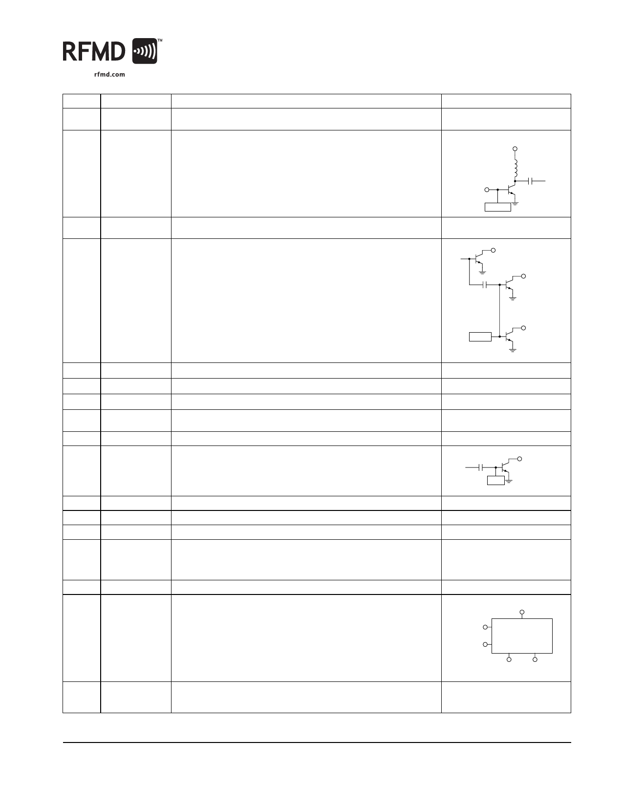
Pin Function Description
Interface Schematic
1
GND
Ground connection. For best performance, keep traces physically short
and connect immediately to ground plane.
2
RF IN
RF input. This input is AC coupled, so an external blocking capacitor is not
VCC1
required if this pin is connected to a DC path.
Bond Wire
Inductance
RF IN
BIAS
3
BIAS GND2 Ground for second stage bias circuit. For best performance, keep traces See pin 16.
physically short and connect immediately to ground plane.
4
PWR SEN The PWR SEN and PWR REF pins can be used in conjunction with an exter-
nal feedback path to provide an RF power control function for the RF2163.
The power control function is based on sampling the RF drive to the final
stage of the RF2163.
RF OUT
PWR SEN
BIAS
PWR REF
5
PWR REF Same as pin 4.
See pin 4.
6
VREG1
This pin requires a regulated supply to maintain the correct bias current. See pin 16.
7
VREG2
Same as pin 6.
See pin 16.
8
BIAS GND1 Ground for first stage bias circuit. For best performance connect to ground See pin 16.
with a 10nH inductor.
9
GND
Same as pin 1.
10
RF OUT
RF output and bias for the output stage. The power supply for the output
transistor needs to be supplied to this pin. This can be done through a
quarter-wave length microstrip line that is RF grounded at the other end, or
through an RF inductor that supports the required DC currents.
BIAS
RF OUT
11
RF OUT Same as pin 10.
See pin 10.
12
RF OUT Same as pin 10.
See pin 10.
13
NC
Not connected.
14
VCC1
Interstage match and bias for first stage output. Connect interstage match- See pin 2.
ing capacitor to t pin with a short trace. Connect low-frequency bypass
capacitors to this pin with a long trace. See evaluation board layout for
details.
15
VCC1
Same as pin 14.
See pin 2.
16
VCC
Power supply pin for the bias circuits. External low frequency bypass capac-
VCC
itors should be connected if no other low frequency decoupling is nearby.
VREG1
VREG2
BIAS
Pkg
Base
GND
Ground connection. The backside of the package should be connected to
the ground plane through a short path, i.e., vias under the device may be
required.
BIAS BIAS
GND1 GND2
See pin 1 and 2.
Rev A6 DS060301
7628 Thorndike Road, Greensboro, NC 27409-9421 · For sales or technical
support, contact RFMD at (+1) 336-678-5570 or sales-support@rfmd.com.
3 of 12
Share Link: 