MC14597B Ver la hoja de datos (PDF) - Motorola => Freescale
Número de pieza
componentes Descripción
Lista de partido
MC14597B Datasheet PDF : 9 Pages
| |||
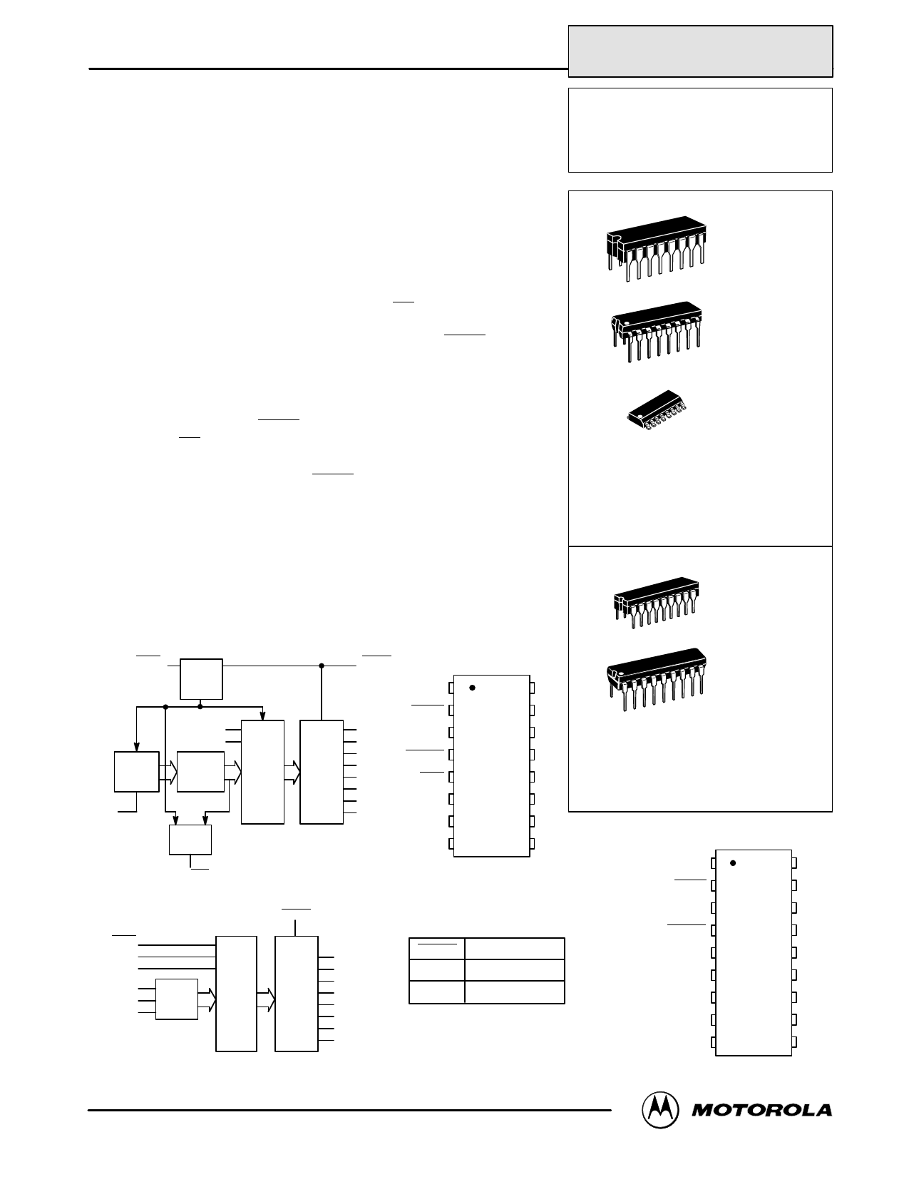
MOTOROLA
SEMICONDUCTOR TECHNICAL DATA
MC14599
See Page 6-174
8-Bit Bus-Compatible Latches
The MC14597B and MC14598B are 8–bit latches, one addressed with an
internal counter and the other addressed with an external binary address.
The 8 latch–outputs are high drive, three–state and bus line compatible. The
drive capability allows direct applications with MPU systems such as the
Motorola 6800 family.
With MC14597B, a 3–bit address counter (clocked on the falling edge of
Increment) selects the appropriate latch. The latches of the MC14598B are
accessed via the Address pins, A0, A1, and A2. A Full Flag is provided on
the MC14597B to indicate the position of the Address counter.
All 8 outputs from the latches are available in parallel when Enable is in the
low state. Data is entered into a selected latch from the Data pin when the
Strobe is high. Master reset is available on both parts.
• Serial Data Input
• Three–State Bus Compatible Parallel Outputs
• Three–State Control Pin (Enable) TTL Compatible Input
• Open Drain Full Flag (Multiple Latch Wire–O Ring)
• Master Reset
• Level Shifting Inputs on All Except Enable
• Diode Protection — All Inputs
• Supply Voltage Range — 3.0 Vdc to 18 Vdc
• Capable of Driving TTL Over Rated Temperature Range
With Fanout as Follows:
1 TTL Load
4 LSTTL Loads
MC14597B
BLOCK DIAGRAMS
RESET 2
RESET
LOGIC
3–BIT
ADDRESS
COUNTER
7
INCREMENT
VDD = 16
VSS = 8
DATA 3
STROBE 6
ADDRESS
DECODER
8
LATCHES
FULL
LOGIC
5
FULL
4 ENABLE
D0 1
RESET 2
1 D0
15 D1
DATA 3
14 D2
THREE 13 D3
STATE 12 D4
OUTPUT 11 D5
BUFFERS 10 D6
9 D7
ENABLE 4
FULL 5
STROBE 6
INCREMENT 7
VSS 8
16 VDD
15 D1
14 D2
13 D3
12 D4
11 D5
10 D6
9 D7
MC14598B
RESET
2
DATA
3
STROBE
6
A0 7
A1 8 ADDRESS
A2 10 DECODER
8
LATCHES
VDD = 18
VSS = 9
ENABLE
4
1 D0
17 D1
THREE
STATE
16 D2
15 D3
OUTPUT 14 D4
BUFFERS 13 D5
12 D6
11 D7
OUTPUT
TRUTH TABLE
Enable
Outputs
1
High Impedance
0
Dn
Dn = State of nth latch
NC = NO CONNECTION
REV 3
1/94
©MMOotoTrOolaR, IOncL. A199C5MOS LOGIC DATA
MC14597B
MC14598B
L SUFFIX
CERAMIC
CASE 620
P SUFFIX
PLASTIC
CASE 648
D SUFFIX
SOIC
CASE 751B
ORDERING INFORMATION
MC14597BCP
MC14597BCL
MC14597BDW
Plastic
Ceramic
SOIC
TA = – 55° to 125°C for all packages.
L SUFFIX
CERAMIC
CASE 726
P SUFFIX
PLASTIC
CASE 707
ORDERING INFORMATION
MC14598BCP
MC14598BCL
Plastic
Ceramic
TA = – 55° to 125°C for all packages.
D0 1
RESET 2
DATA 3
ENABLE 4
NC 5
STROBE 6
A0 7
A1 8
VSS 9
18 VDD
17 D1
16 D2
15 D3
14 D4
13 D5
12 D6
11 D7
10 A2
MC14597B MC14598B
1
Share Link: 