IL256AT Ver la hoja de datos (PDF) - Infineon Technologies
Número de pieza
componentes Descripción
Lista de partido
IL256AT Datasheet PDF : 3 Pages
| |||
IL256AT
AC Input Phototransistor
Small Outline Surface Mount
Optocoupler
FEATURES
• Guaranteed CTR Symmetry, 2:1 Maximum
• Bidirectional AC Input
Industry Standard SOIC-8 Surface
• Mountable Package
• Standard Lead Spacing, .05"
• Available only on Tape and Reel Option
(Conforms to EIA Standard RS481A)
• Underwriters Lab File #E52744
(Code Letter Y)
DESCRIPTION
The IL256A is an AC input phototransistor opto-
coupler. The device consists of two infrared emit-
ters connected in anti-parallel and coupled to a
silicon NPN phototransistor detector.
These circuit elements are constructed with a
standard SOIC-8 foot print.
The product is well suited for telecom applica-
tions such as ring detection or off/on hook status,
given its bidirectional LED input and guaranteed
current transfer ratio (CTR) minimum of 20% at
IF=10 mA.
Maximum Ratings
Emitter
Continuous Forward Current ...................... 60 mA
Power Dissipation at 25°C......................... 90 mW
Derate Linearly from 25°C................... 0.8 mW/°C
Detector
Collector-Emitter Breakdown Voltage............ 30 V
Emitter-Collector Breakdown Voltage........... 5.0 V
Collector-Base Breakdown Voltage............... 70 V
Power Dissipation ................................... 150 mW
Derate Linearly from 25°C................... 2.0 mW/°C
Package
Total Package Dissipation at 25°C Ambient
(LED + Detector) ................................. 240 mW
Derate Linearly from 25°C.................... 3.2mW/°C
Storage Temperature ................ –55°C to +150°C
Operating Temperature ............ –55°C to +100°C
Soldering Time at 260°C ........................... 10 sec.
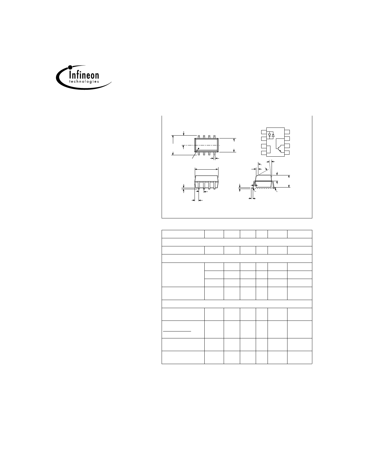
Dimensions in inches (mm)
.120±.005
(3.05±.13)
.240
(6.10)
Anode/
Cathode
1
Cathode/
CL
.154 ±.005
(3.91± .13)
Anode
NC
2
3
NC 4
Pin One ID
.016 (.41)
.192 ± .005
(4.88± .13)
.015 ± .002
40°
(.38± .05)
8 NC
7 Base
6 Collector
5 Emitter
7°
.058 ± .005
(1.49± .13)
.004 (.10)
.008 (.20)
.008 (.20)
5°max.
.125 ±.005
(3.18 ±.13)
.050 (1.27)
typ.
.020 ± .004
.021 (.53)
(.51 ± .10)
2 plcs.
R.010
Lead
(.25) max. Coplanarity
± .0015 (.04)
max.
Characteristics TA=25°C
Symbol Min.
Emitter
Forward Voltage
VF
—
Detector
Breakdown Voltage BVCEO 30
BVECO 5.0
BVCBO 70
Leakage Current,
ICEO
—
Collector-Emitter
Package
DC Current Transfer CTR
20
Ratio
Symmetry
—
0.5
CTR at +10mA
CTR at –10 mA
Saturation Voltage, VCEsat —
Collector-Emitter
Isolation Voltage,
VIO
Input to Output
3000
Typ.
1.2
50
10
90
5.0
—
1.0
—
—
Max. Unit
1.5 V
—V
—V
—V
50 nA
—%
2.0 —
0.4 —
— VRMS
Condition
IF=±10 mA
IC=1.0 mA
IE=100 µA
IC=100 µA
VCE=10 V
IF=±10 mA,
VCE=5.0 V
—
IF=±16 mA,
IC=2.0 mA
—
2001 Infineon Technologies Corp. • Optoelectronics Division • San Jose, CA
www.infineon.com/opto • 1-888-Infineon (1-888-463-4636)
2–125
April 3, 2000-18
Share Link: 