DS2118MB Ver la hoja de datos (PDF) - Maxim Integrated
Número de pieza
componentes Descripción
Lista de partido
DS2118MB Datasheet PDF : 11 Pages
| |||
DS2118M
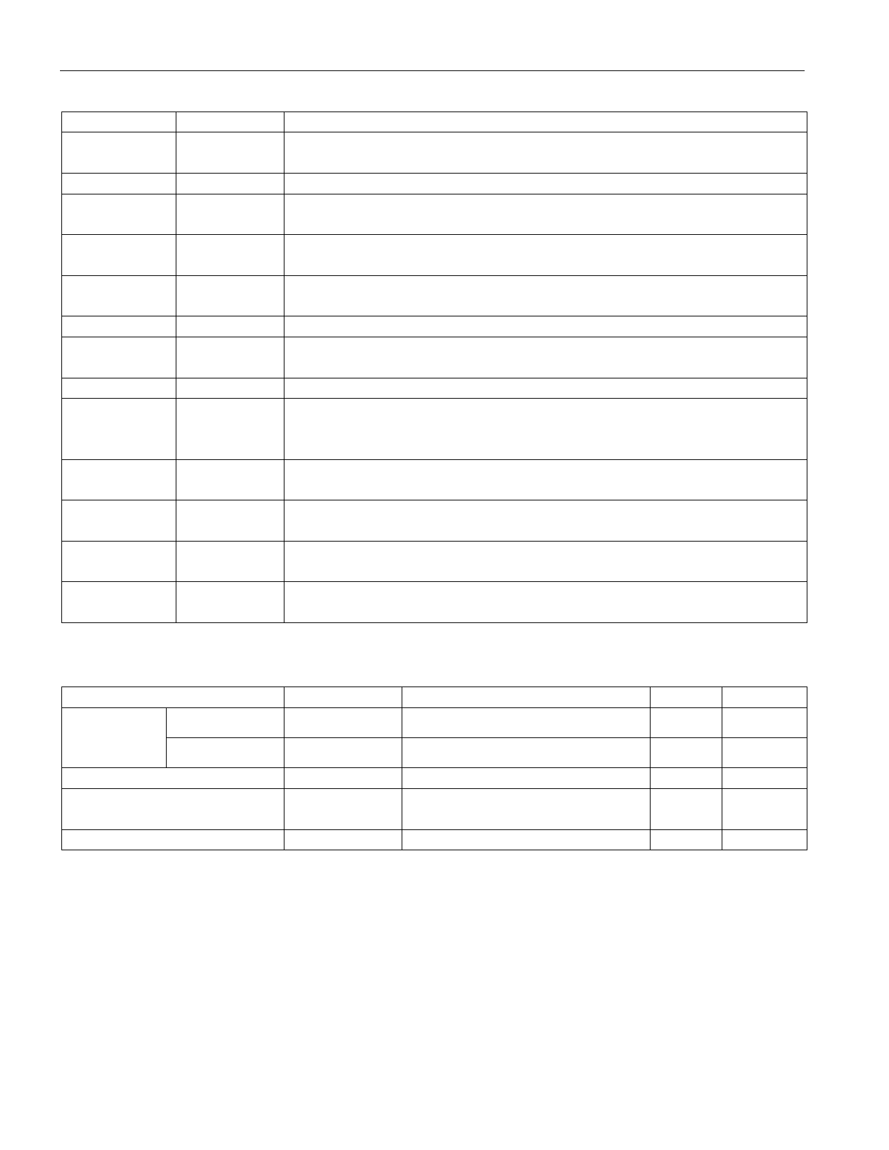
PIN DESCRIPTION
PIN
NAME
1
VREF
2, 3
4–7, 11–16,
22–25, 29–32
8, 10, 26, 9,
28, 27
NC
RxP,
RxN
HS GND
17
ISO
18
GND
19
MSTR/SLV
20
DIFFSENSE
21
DIFF_CAP
33
SE
34
LVD
35
HVD
36
TPWR
FUNCTION
Reference Voltage. 2.85V reference in SE mode and 1.25V reference in
LVD mode; must be decoupled with a 4.7µF cap.
No Connection. Do not connect these pins.
Signal Termination. Connect to SCSI bus signal lines.
Heat Sink Ground. Internally connected to the mounting pad. Should
be grounded.
Isolation. When pulled high, the DS2118M isolates its bus pins (RxP,
FxP) from the SCSI bus.
Ground. Signal ground; 0V.
Master/Slave. Mode-select for the noncontrolling terminator. When
pulled high (MSTR), the DIFFSENSE driver is enabled.
DIFFSENSE. Output to drive the SCSI bus DIFFSENS line.
DIFFSENSE Capacitor. Connect 0.1µF capacitor for DIFFSENSE
filter. Input to detect the type of device (differential or single-ended) on
the SCSI bus.
Single-Ended. SE output of DIFFSENSE receiver; indicates SE bus
operation.
Low-Voltage Differential. LVD output of DIFFSENSE receiver;
indicates LVD bus operation.
High-Voltage Differential. HVD output of DIFFSENSE receiver;
indicates HVD bus operation or thermal shutdown.
Termination Power. Connect to the SCSI TERMPWR line and
decouple with 2.2µF capacitor.
RECOMMENDED OPERATING CONDITIONS
PARAMETER
SYMBOL MIN
Termpower SE Mode
VTPWR(SE)
4.0
Voltage
LVD Mode
VTPWR(LVD)
2.7
Logic 0
VIL
-0.3
Logic 1
VIH
2.0
Operating Temperature
VAMB
0
TYP
MAX
5.5
5.5
+0.8
VTPWR +
0.3
70
UNITS
V
V
V
V
°C
NOTES
7 of 10
Share Link: 