PI74LPT162Q952CA Ver la hoja de datos (PDF) - Pericom Semiconductor
Número de pieza
componentes Descripción
Lista de partido
PI74LPT162Q952CA Datasheet PDF : 5 Pages
| |||
PI74LPT162Q952 1122334455667788990011223344556677889900112233445566778899001122112233445566778899001122334455667788990011223344556677889900112211223344556677889900112233445566778899001122334455667788990011221122334455667788990011223344556677889900112233445566778899001122112233445566778899001122
Fast CMOS 3.3V
16-Bit Registered Transceivers
Product Features
Compatible with LCX and LVT families of products
Supports 5V Tolerant Mixed Signal Mode Operation
Input can be 3V or 5V
Output can be 3V or connected to 5V bus
Advanced Low Power CMOS Operation
Excellent output drive capability:
Balanced drives (12mA sink and source)
25-Ohm Series resistor on outputs to reduce
overshoot and undershoot
Pin compatible with industry standard
double-density pinouts
Low ground bounce outputs
Hysteresis on all inputs
Industrial operating temperature range: 40°C to +85°C
Multiple center pins and distributed Vcc/GND pins
minimize switching noise
Packages available:
56-pin 240 mil wide plastic TSSOP (A)
56-pin 300 mil wide plastic SSOP (V)
Product Description
Pericom Semiconductors PI74LPT series of logic circuits are
produced in the Companys advanced 0.6 micron CMOS technology,
achieving industry leading speed grades.
The PI74LPT162Q952 has 16-bit registered transceivers organized
with two sets of eight D-type latches with separate input and output
controls for each set. For data flow from A to B, for example, the
A-to-B Enable (xCEAB) input must be LOW to enter data from xAx.
The data present on the A port will be clocked on the B register when
xCLKAB toggles from LOW-to-HIGH. The xOEAB control performs
the output enable function on the B port. Control of data from B to
A is similar, but uses the xCEAB, xCLKAB, and xOEAB inputs. By
connecting the control pins of the two independent transceivers
together, a full 16-bit operation can be achieved. The output buffers
are designed with a Power-Off disable allowing live insertion of
boards when used as backplane drivers.
The PI74LPT162Q952 can be driven from either 3.3V or 5.0V devices
allowing this device to be used as a translator in a mixed
3.3/5.0V system.
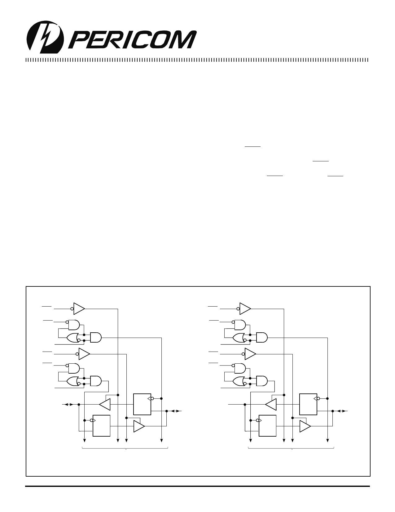
Logic Block Diagram
1OEBA
1CEBA
1CLKBA
1OEAB
1CEAB
1CLKAB
1A0
C
D
C
D
TO 7 OTHER CHANNELS
2OEBA
2CEBA
2CLKBA
2OEAB
2CEAB
2CLKAB
2A0
1B0
C
D
2B0
C
D
TO 7 OTHER CHANNELS
1
PS8098A 02/25/97
Share Link: 