F7103Q Ver la hoja de datos (PDF) - International Rectifier
Número de pieza
componentes Descripción
Lista de partido
F7103Q Datasheet PDF : 10 Pages
| |||
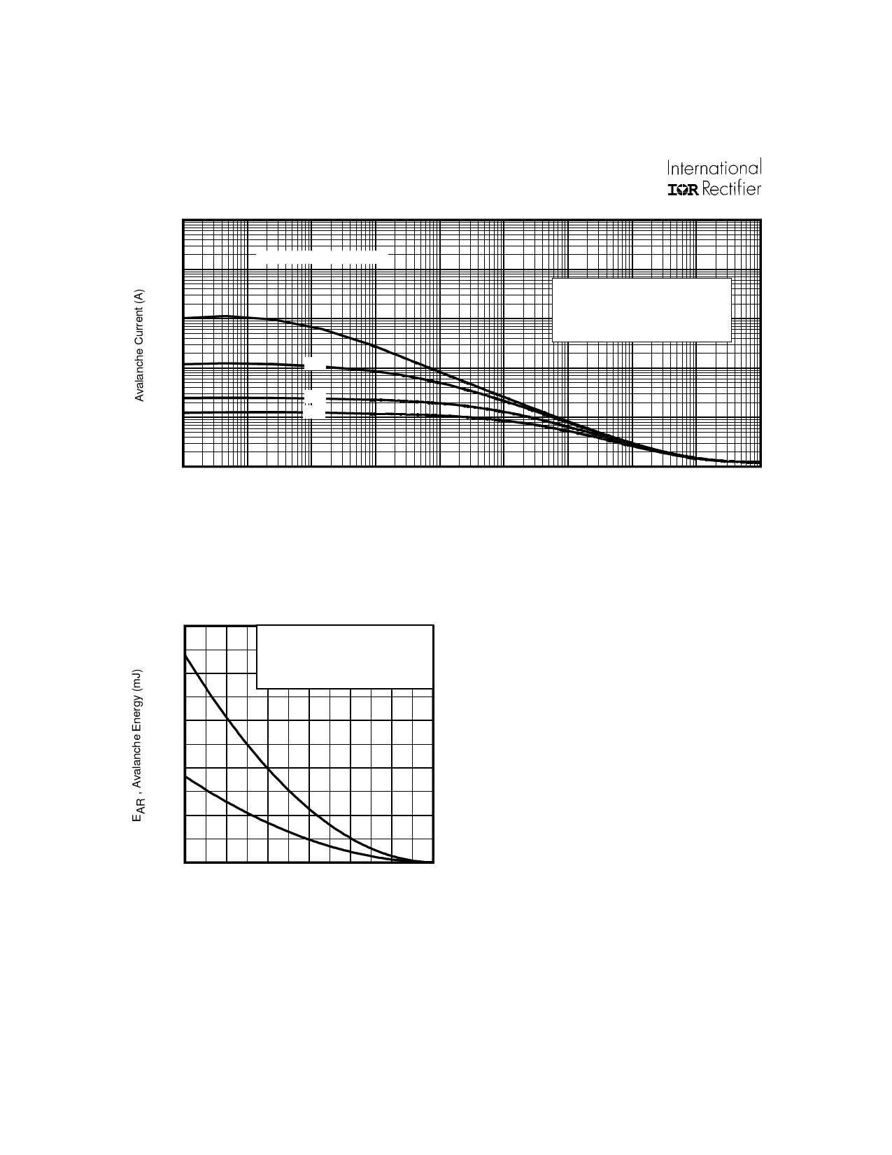
IRF7103Q
1000
100
Duty Cycle = Single Pulse
10
1
0.01
0.05
0.1
0.10
Allowed avalanche Current vs
avalanche pulsewidth, tav
assuming ∆ Tj = 25°C due to
avalanche losses
0.01
1.0E-08
1.0E-07
1.0E-06
1.0E-05
1.0E-04
1.0E-03
tav (sec)
1.0E-02
1.0E-01
Fig 19. Typical Avalanche Current Vs.Pulsewidth
1.0E+00
1.0E+01
25
TOP
Single Pulse
BOTTOM 10% Duty Cycle
20
ID = 3.0A
15
10
5
0
25
50
75
100 125 150
Starting T J , Junction Temperature (°C)
Notes on Repetitive Avalanche Curves , Figures 15, 16:
(For further info, see AN-1005 at www.irf.com)
1. Avalanche failures assumption:
Purely a thermal phenomenon and failure occurs at a
temperature far in excess of Tjmax. This is validated for
every part type.
2. Safe operation in Avalanche is allowed as long asTjmax is
not exceeded.
3. Equation below based on circuit and waveforms shown in
Figures 12a, 12b.
4. PD (ave) = Average power dissipation per single
avalanche pulse.
5. BV = Rated breakdown voltage (1.3 factor accounts for
voltage increase during avalanche).
6. Iav = Allowable avalanche current.
7. ∆T = Allowable rise in junction temperature, not to exceed
Tjmax (assumed as 25°C in Figure 15, 16).
175
tav = Average time in avalanche.
D = Duty cycle in avalanche = tav ·f
ZthJC(D, tav) = Transient thermal resistance, see figure 11)
Fig 20. Maximum Avalanche Energy
Vs. Temperature
PD (ave) = 1/2 ( 1.3·BV·Iav) = ∆T/ ZthJC
Iav = 2∆T/ [1.3·BV·Zth]
EAS (AR) = PD (ave)·tav
8
www.irf.com
Share Link: 