XR16C864 Ver la hoja de datos (PDF) - Exar Corporation
Número de pieza
componentes Descripción
Lista de partido
XR16C864 Datasheet PDF : 51 Pages
| |||
XR16C864
2.97V TO 5.5V QUAD UART WITH 128-BYTE FIFO
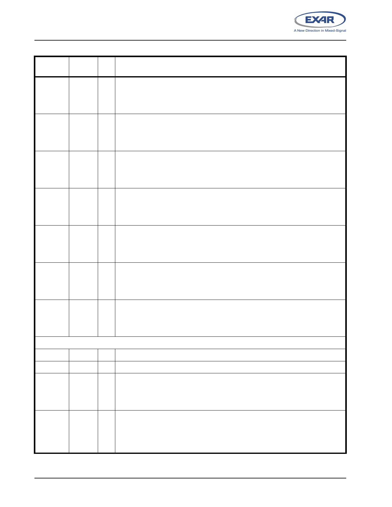
Pin Description
REV. 2.2.0
NAME
100-QFP
TYPE
PIN #
DESCRIPTION
CTSA#
8
I UART channels A-D Clear-to-Send (active low) or general purpose input. It can be used
CTSB#
22
CTSC#
59
for auto CTS flow control, see EFR[7], and IER[7]. Also see Figure 10. These inputs
should be connected to VCC when not used.
CTSD#
73
DTRA#
DTRB#
DTRC#
DTRD#
9
O UART channels A-D Data-Terminal-Ready (active low) or general purpose output. If
21
these outputs are not used, leave them unconnected.
60
72
DSRA#
7
I UART channels A-D Data-Set-Ready (active low) or general purpose input. This input
DSRB#
23
should be connected to VCC when not used.
DSRC#
58
DSRD#
74
CDA#
CDB#
CDC#
CDD#
99
I UART channels A-D Carrier-Detect (active low) or general purpose input. This input
32
should be connected to VCC when not used.
49
83
RIA#
RIB#
RIC#
RID#
98
I UART channels A-D Ring-Indicator (active low) or general purpose input. This input
33
should be connected to VCC when not used.
48
84
OP1A#
OP1B#
OP1C#
OP1D#
3
O General purpose output or RS-485 direction control signal. RS-485 direction control can
28
be selected via FCTR bit-3. SEE”AUTO RS485 HALF-DUPLEX CONTROL” ON
53
PAGE 20. If these outputs are unused, leave them unconnected.
78
OP2A#
OP2B#
OP2C#
OP2D#
2
O General purpose output. If these outputs are unused, leave them unconnected.
29
52
79
ANCILLARY SIGNALS
XTAL1
40
I Crystal or external clock input. This input is not 5V tolerant.
XTAL2
41
O Crystal or buffered clock output.
BCLKA
BCLKB
BCLKC
BCLKD
1
O Baud Rate Generator Output. The baud rate generator clock output is internally con-
30
nected to the RCLK input. This pin provides the 16X clock of the selected data rate from
51
the baud rate generator.
80
16/68#
36
I Intel or Motorola Bus Select (input with internal pull-up).
When 16/68# pin is at logic 1, 16 or Intel Mode, the device will operate in the Intel bus
type of interface.
When 16/68# pin is at logic 0, 68 or Motorola mode, the device will operate in the Motor-
ola bus type of interface.
6
Share Link: 