HS-82C55ARH Ver la hoja de datos (PDF) - Intersil
Número de pieza
componentes Descripción
Lista de partido
HS-82C55ARH Datasheet PDF : 17 Pages
| |||
HS-82C55ARH
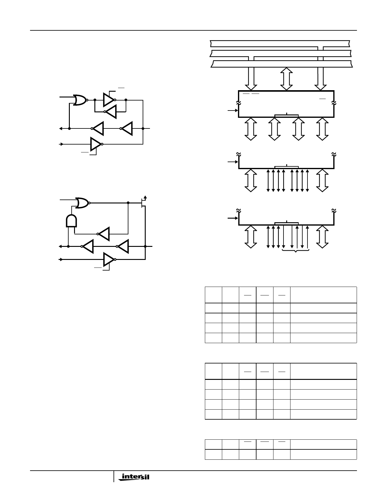
Port C
One 8-bit data output latch/buffer and one 8-bit data input
buffer (no latch for input). This port can be divided into two
4-bit ports under the mode control. Each 4-bit port contains
a 4-bit latch and can be used for the control signal outputs
and status signal inputs in conjunction with Ports A and B.
See Figure 9B.
ADDRESS BUS
CONTROL BUS
DATA BUS
MASTER
RESET
RD
CONTROL
INTERNAL
DATA IN
INTERNAL
DATA OUT
WR
SIGNAL
FIGURE 9A.
MASTER
RESET
EXTERNAL
PORT A PIN
VDD
P
INTERNAL
DATA IN
INTERNAL
DATA OUT
WR
SIGNAL
EXTERNAL
PORT B, C
PIN
FIGURE 9B.
FIGURE 9. I/O PORT CONFIGURATION
Operational Description
Control Word
The data direction and mode of Ports A, B and C are
determined by the contents of the Control Word. See
Figure 11. The Control Word can be both written and read as
shown in Table 1 and 2. During write operations, the function
of the Control Word being written is determined by data bit
D7. If D7 is low, the data on D0 - D3 will set or reset one of
the bits of Port C. See Figure 12. During read Operations,
the Control Word will always be in the format illustrated in
Figure 11 with Bit D7 high to indicate Control Word Mode
Information.
MODE 0
RD, WR
B
D7 - D0
C
A0 - A1
CS
A
8 I/O
4 I/O
4 I/O
8 I/O
PB7 - PB0 PC3 - PC0 PC7 - PC4 PA7 - PA0
MODE 1
B
C
A
8 I/O
8 I/O
PB7 - PB0 CONTROL CONTROL PA7 - PA0
OR I/O OR I/O
MODE 2
B
C
A
8 I/O
8
BIDIREC-
TIONAL
PB7 - PB0 I/O
PA7 - PA0
CONTROL
FIGURE 10. BASIC MODE DEFINITIONS AND BUS INTERFACE
TABLE 1.
A1 A0 RD WR CS
INPUT OPERATION
(READ)
0
0
0
1
0 Port A - Data Bus
0
1
0
1
0 Port B - Data Bus
1
0
0
1
0 Port C - Data Bus
1
1
0
1
0 Control Word - Data Bus
TABLE 2.
A1 A0 RD WR CS
OUTPUT OPERATION
(WRITE)
0
0
1
0
0 Data Bus - Port A
0
1
1
0
0 Data Bus - Port B
1
0
1
0
0 Data Bus - Port C
1
1
1
0
0 Data Bus - Control Word
TABLE 3.
A1 A0 RD WR CS
DISABLE FUNCTION
X
X
X
X
1 Data Bus - 3-State
7
Share Link: 