M30220 Ver la hoja de datos (PDF) - MITSUBISHI ELECTRIC
Número de pieza
componentes Descripción
Lista de partido
M30220 Datasheet PDF : 212 Pages
| |||
Unddeevrelopment
Tentative Specifications REV.E
Specifications in this manual are tentative and subject to change.
Mitsubishi microcomputers
M30220 Group
SINGLE-CHIP 16-BIT CMOS MICROCOMPUTER
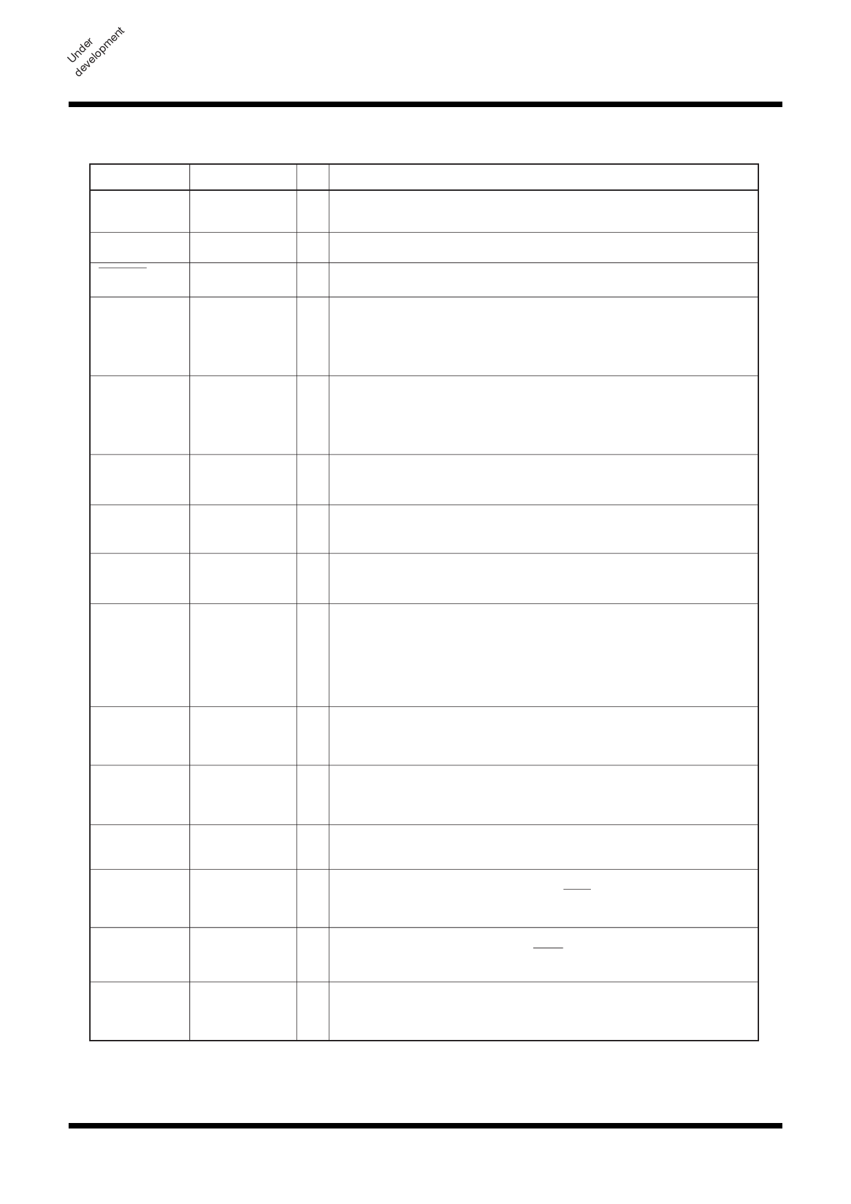
Pin Description
Pin Description
Pin name
VCC, VSS
CNVSS
RESET
Signal name I/O
Function
Power supply
input
Supply 2.7 to 5.5 V to the VCC pin. Supply 0 V to the VSS pin.
CNVSS
I Connect it to the VSS pin.
Reset input
I A “L” on this input resets the microcomputer.
XIN
XOUT
XCIN
XCOUT
Clock input
Clock output
Clock input
Clock output
I These pins are provided for the main clock generating circuit.
O
Connect a ceramic resonator or crystal between the XIN and the
XOUT pins. To use an externally derived clock, input it to the XIN
pin and leave the XOUT pin open.
I These pins are provided for the sub clock generating circuit.
Connect a ceramic resonator or crystal between the XCIN and the
O XCOUT pins. To use an externally derived clock, input it to the
XCIN pin and leave the XCOUT pin open.
AVCC
AVSS
Analog power
supply input
Analog power
supply input
This pin is a power supply input for the A-D converter. Connect
it to VCC.
This pin is a power supply input for the A-D converter. Connect
it to VSS.
VREF
P00 to P07
P10 to P17
P20 to P27
P30 to P35
P40 to P47
P50 to P57
P60 to P67
Reference
voltage input
I This pin is a reference voltage input for the A-D converter.
I/O port P0
I/O port P1
I/O port P2
I/O This is an 8-bit CMOS I/O port. It has an input/output port
direction register that allows the user to set each pin for input or
output individually. When set for input, the user can specify in
units of four bits via software whether or not they are tied to a
pull-up resistor. Pins in this port also use as LCD segment
output and real time port output.
I/O This is an 8-bit I/O port equivalent to P0. Pins in this port also
function as input pins for the key input interrupt function and real
time port output.
I/O This is an 8-bit I/O port equivalent to P0. Pins in this port also
function as input pins for the key input interrupt function and real
time port output.
I/O port P3
I/O port P4
I/O port P5
I/O port P6
I/O This is a 6-bit I/O port equivalent to P0. P30 to P33 also function
as input pins for the key input interrupt function.
I/O This is a 8-bit I/O port equivalent to P0. Pins in this port also
function as timer A0 to A3 I/O pins, INT4 input pin as selected
by software.
I/O This is a 8-bit I/O port equivalent to P0. Pins in this port also
function as timer B0 to B5 and INT3 input pins, CKOUT output
pin as selected by software.
I/O This is an 8-bit I/O port equivalent to P0. Pins in this port also
function as UART0 and UART1 I/O pins as selected by
software.
6
Share Link: 