M5295AL Ver la hoja de datos (PDF) - MITSUBISHI ELECTRIC
Número de pieza
componentes Descripción
Lista de partido
M5295AL Datasheet PDF : 8 Pages
| |||
MITSUBISHI<Dig.Ana.INTERFACE>
M5295AL/P/FP
WATCHDOG TIMER
(2)Detection voltage 2(VTH2(L))adjustment
VTH2(L)(V) R3(kΩ) R4(kΩ) ∆VTH2(mV) Detection voltage calculation formula
13 10 0.93 16.3
10
10
1.26
16.3
VTH2(L)= R03+R04
R04
X1.24(V)
R3
51.2k
6
7
10 1.99 16.3
5
10 3.24 16.3
RL 4.6
100
R03=R3//51.2kΩ
R04=R4//18.8kΩ
5
+
-
7
R4
18.8k
1.24V
4 10.61 5
3.5 8.38 5
17.2
14.1
∆VTH2= R03 X100(mV)
51.2k
To adjust detection voltage 2,determine external resistance
with the following equations:
4
a. VTH2(L)>4.6V(R3=10kΩ)
1
R4=
1
1
-
R0 18.8k
R0= 8.37kX1.24
VTH2(L)-1.24
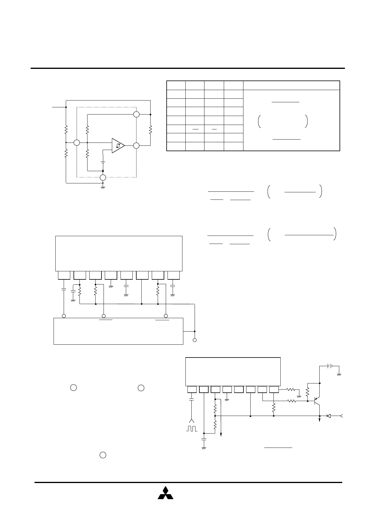
APPLICATION EXAMPLE
M5295AL
b. VTH2(L)<4.6V(R4=5kΩ)
R3=
1
1
-
1
R0 51.2k
R0= (VTH2(L)-1.24)3.95k
1.24
1
2
3
4
5
6
7
8
CLOCK
RST1
(RESET)
MCU/MPU
OPERATION INSTRUCTIONS
RST2
(HOLD)
VDD
Example of Backup Circuit with M5295AL
BACKUP POWER SUPPLY
1.When malfunction occurs due to noise or other related
trouble,connect capacitance of approximately 1000pF
between pin 5 and GND as well as pin 8 and GND to
stabilize operation.
2.To adjust detection voltage,add resistance of 15kΩ
or less to both Vcc and GND via adjusting pins.
(Set detection voltage to no less than 3V.)
3.Set tWD and tRST(2) as shown below:
110µs≤tWD≤1.1s
8.3µs≤tRST(2)≤83ms
10kΩ≤R1≤30kΩ
4.Input clock pulses to pin 1 via capacitor.To determine
capacitance,refer to "Relationship between Input Pulse
Width and Input Capacitance Cin".
M5295AL
1 23 4 56 78
3.5V
10KΩ
R4
R3
Vcc
RESET
OUTPUT
Backup switching voltage
TO SYSTEM
VTH(L)
Switching voltage calculation formula
VTH2(L)= R03+R04 X1.24
R04
R03=R3//51.2k
R04=R4//18.8k
(Note)Set backup switching voltage to be more
than or equal to backup supply voltage.
MITSUBISHI
ELECTRIC
( 6/8 )
Share Link: 