DM9008 Ver la hoja de datos (PDF) - Davicom Semiconductor, Inc.
Número de pieza
componentes Descripción
Lista de partido
DM9008 Datasheet PDF : 68 Pages
| |||
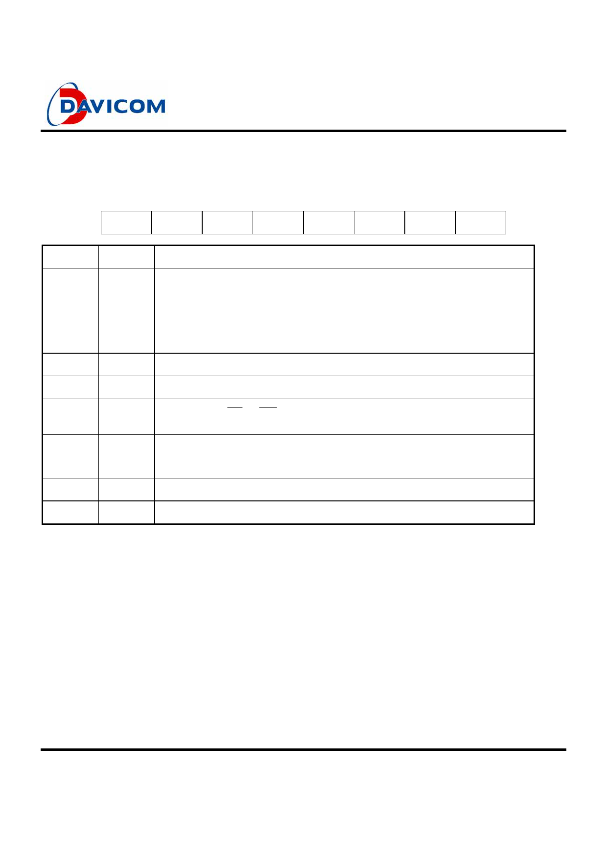
Configuration Register B (CRB)
DM9008
ISA/Plug & Play Super Ethernet Contoller
Configuration Register B can be read at address 0BH in Page 0 of ENC, and can be written by following a read to address 0BH with a
write to address 0BH. If a write to address 0BH is performed without a previous read to 0BH, it will be regarded as a write to register
RBCR1 of ENC.
7
6
5
4
3
2
1
0
--
--
BUSERR CHRDY
--
GDLINK PHYS1 PHYS0
Bit
Symbol
Description
0, 1
PHYS0 Physical Media Interfaces: These two bits determine which type of physical interface the
PHYS1 DM9008 is using, as shown below:
bit1
bit0
Interface
0
0
Set to 10BASE-T; BNCEN = low
0
1
Set to 10BASE2; BNCEN = high
1
0
Set to 10BASE5; BNCEN = low
1
1
Auto-detection media
2
GDLINK Read: Link status. One indicates Link OK; zero indicates Link Fail
3
--
Reserved
4
CHRDY IOCHRDY from IOR or IOW or from BALE: When low, DM9008 will pull IOCHRDY low after
the command strobe. If high, IOCHRDY will be pulled low after BALE goes high
5
BUSERR Bus Error: This bit shows that DM9008 has detected an ISA bus error. This bit will be high if
DM9008 inserts wait states into a system access and the system terminates the cycle without
inserting wait states
6
--
Reserved
7
--
Reserved
Final
11
Version: DM9008-DS-F02
November 30, 2000
Share Link: 