FDC87W21 Ver la hoja de datos (PDF) - SMSC -> Microchip
Número de pieza
componentes Descripción
Lista de partido
FDC87W21 Datasheet PDF : 164 Pages
| |||
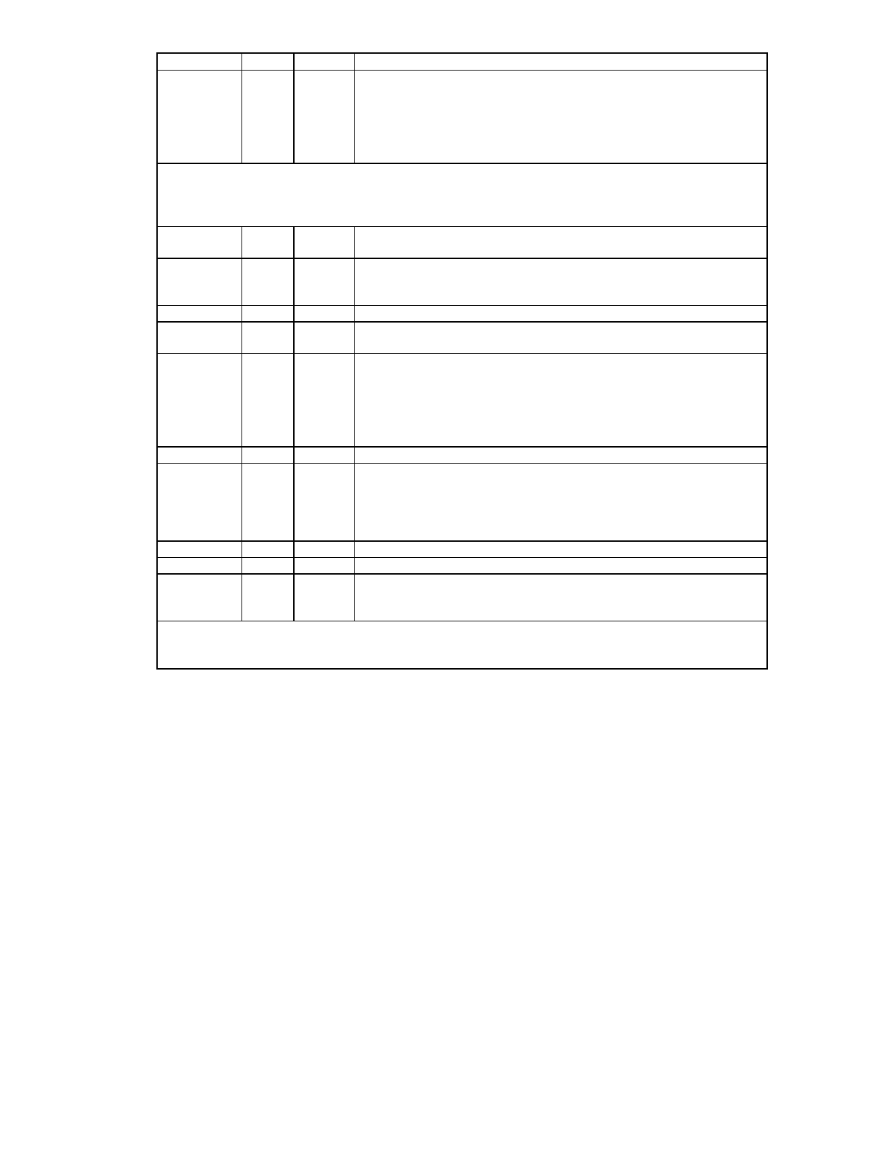
SYMBOL PIN
I/O
FUNCTION
nRTSB
45
O8tc
UART B Request To Send. An active low informs the modem or
data set that the controller is ready to send data.
PGOIQSEL
I8tc
During power-on reset, this pin is pulled down internally and is
defined as PGOIQSEL, which provides the power-on value for
CR16 bit 4 (GOIQSEL). A 4.7 k is recommended when intends to
pull up at power-on reset.
Game Port/Power Down Interface
If Bit 3 of CR16 (GMDRQ) is 1, Bit 4 of CR3 (GMODS0) determines whether the game port is in
Adapter mode or Portable mode (default is Adapter mode). If Bit 3 of CR16 is 0, pin 39 and 41 are
used for DMA A operation.
nGMRD
41 OUT8t When CR16 Bit 3 (GMDRQ) = 1, Adapter mode: Game port read
control signal.
PFDCEN
OUT8t Portable mode: When parallel port is selected as Extension
FDD/Extension 2FDD mode, this pin will be active. The active state
is dependent on bit 7 of CRA (PFDCACT), and default is low active.
nDACK_A
INt When CR16 Bit 3 (GMDRQ) = 0, DMA acknowledge signal A.
nGMWR
39 OUT8t When CR16 Bit 3 (GMDRQ) = 1, Adapter mode: Game port write
control signal.
PEXTEN
OUT8t Portable mode: When a particular extended mode is selected for
the parallel port, this pin will be active. The extended modes
include Extension Adapter mode, EPP mode, ECP mode, and
ECP/EPP mode, which are selected using bit 3 - bit 0 of CRA. The
active state is dependent on bit 6 of CRA (PEXTACT); the default is
low active.
DRQ_A
OUT8t When CR16 Bit 3 (GMDRQ) = 0: DMA request signal A.
PDCIN
3
INt This input pin controls the chip power down. When this pin is
active, the clock supply to the chip will be inhibited and the output
pins will be tri-stated as defined in CR4 and CR6. The PDCIN is
pulled down internally. Its active state is defined by bit 4 of CRA
(PDCHACT). Default is high active.
nDACK_N
INt DMA acknowledge signal D.
IRSL1
OUT12t IR module mode select 1.
IRRXH/
IRSL0
I/O12t When input pin, high speed IR received terminal. When as output
pin, IR module mode select 0. Input or output are definied in high
speed IR register.
Multi-Mode Parallel Port
The following pins have eight functions, which are controlled by bits PRTMOD0, PRTMOD1, and
PRTMOD2 of CR0 and CR9. (Refer to the Extended Functions Section).
9
Share Link: 