5962R9571401QRC(1996) Ver la hoja de datos (PDF) - Intersil
Número de pieza
componentes Descripción
Lista de partido
5962R9571401QRC Datasheet PDF : 6 Pages
| |||
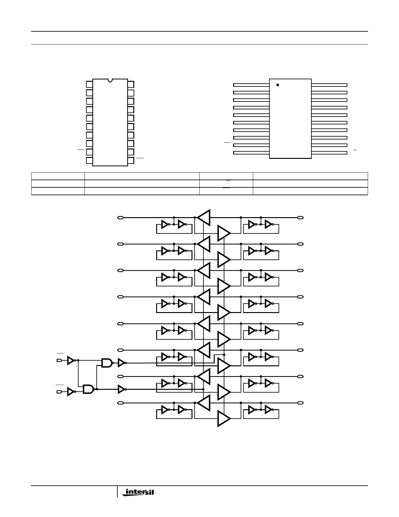
HS-82C08RH
Pinouts
20 LEAD CERAMIC DUAL-IN-LINE
METAL-SEAL PACKAGE (SBDIP) MIL-STD-1835, CDIP2-T20
TOP VIEW
A0 1
A1 2
A2 3
A3 4
A4 5
A5 6
A6 7
A7 8
OE 9
GND 10
20 VDD
19 B0
18 B1
17 B2
16 B3
15 B4
14 B5
13 B6
12 B7
11 T/R
20 LEAD CERAMIC METAL SEAL
FLATPACK PACKAGE (FLATPACK) MIL-STD-1835, CDFP4-F20
TOP VIEW
A0
A1
A2
A3
A4
A5
A6
A7
OE
GND
1
20
2
19
3
18
4
17
5
16
6
15
7
14
8
13
9
12
10
11
VDD
B0
B1
B2
B3
B4
B5
B6
B7
T/R
PIN
A0-A7
B0-B7
DESCRIPTION
Local Bus Data I/O Pins
System Bus Data I/O Pins
PIN
DESCRIPTION
T/R
Transmit/Receive Input
OE
Active Low Output Enable
Logic Diagram
A0 1
A1 2
A2 3
A3 4
A4 5
OE 9
T/R11
A5 6
B ENABLE
A6 7
A ENABLE
A7 8
TSB
TSB
TSB
TSB
TSB
TSB
TSB
TSB
TSB
TSB
TSB
TSB
TSB
TSB
TSB
TSB
19 B0
18 B1
17 B2
16 B3
15 B4
14 B5
13 B6
12 B7
NOTE: An Important caveat that is applicable to CMOS devices in general is that unused inputs should never be left floating. This rule applies
to inputs connected to a three-state bus. The need for external pull-up resistors during three-state bus conditions is eliminated by the
presence of regenerative latches on the following HS-82C08RH pins. A0-7 and B0-7 The functional block diagram depicts one of
these pins with the regenerative latch. When the CMOS driver assumes the high impedance state, the latch holds the bus in whatever
logic state (high or low) it was before the three-state condition. A transient drive current of ±1.5mA at VDD/2 ±0.5V for 10ns is required
to switch the latch. Thus, CMOS device inputs connected to the bus are not allowed to float during three-state conditions.
Spec Number 518057
2
Share Link: 