DCR1003SF Ver la hoja de datos (PDF) - Dynex Semiconductor
Número de pieza
componentes Descripción
Lista de partido
DCR1003SF Datasheet PDF : 8 Pages
| |||
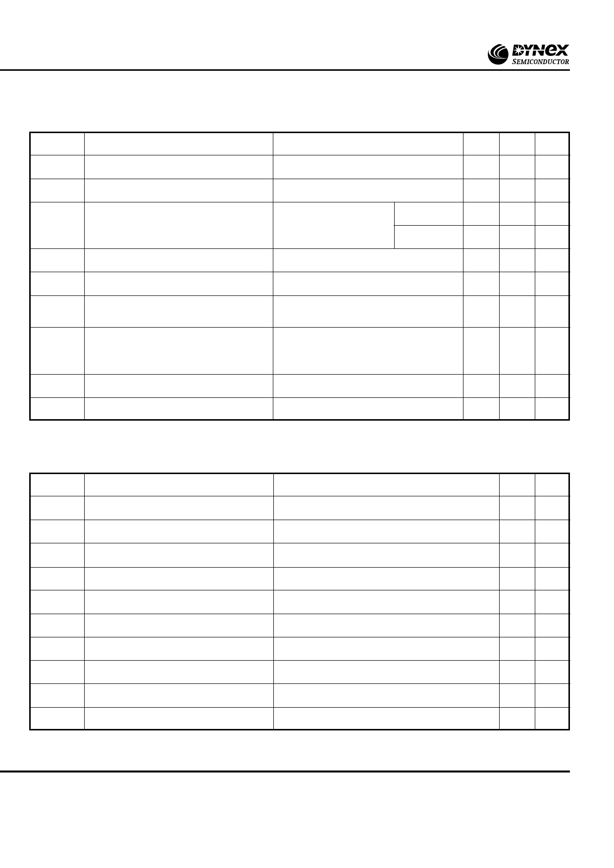
DCR1003SF
DYNAMIC CHARACTERISTICS
Symbol
Parameter
Conditions
Typ. Max. Units
I /I
RRM DRM
dV/dt
dI/dt
VT(TO)
r
T
tgd
tq
Peak reverse and off-state current
At V /V , T = 125oC
-
RRM DRM case
Maximum linear rate of rise of off-state voltage To 67% VDRM Tj = 125oC.
-
Rate of rise of on-state current
From 67% VDRM to 1000A Repetitive 50Hz -
Gate source 1.5A
tr = 0.5µs. Tj = 125oC.
Non-repetitive -
Threshold voltage
At Tvj = 125oC
-
On-state slope resistance
Delay time
Turn-off time
At T = 125oC
-
vj
VD = 67% VDRM, Gate source 30V, 15Ω
Rise time 0.5µs, Tj = 25oC
-
I = 800A, t = 1ms, T = 125˚C,
T
p
j
VRM = 50V, dIRR/dt = 20A/µs,
110
V
DR
=
50%
V,
DRM
dV /dt
DR
=
20V/µs
linear
100 mA
1000 V/µs
500 A/µs
1000 A/µs
0.86 V
0.25 mΩ
1.1
µs
200 µs
IL
Latching current
IH
Holding current
Tj = 25oC, VD = 5V
Tj = 25oC, Rg-k = ∞
-
350 mA
-
230 mA
GATE TRIGGER CHARACTERISTICS AND RATINGS
Symbol
Parameter
VGT
I
GT
VGD
IGD
V
FGM
VFGN
VRGM
IFGM
P
GM
PG(AV)
Gate trigger voltage
Gate trigger current
Gate non-trigger voltage
Gate non-trigger current
Peak forward gate voltage
Peak forward gate voltage
Peak reverse gate voltage
Peak forward gate current
Peak gate power
Mean gate power
Conditions
VDRM = 5V, Tcase = 25oC
VDRM = 5V, Tcase = 25oC
At 67% VDRM Tcase = 125oC
At 67% VDRM Tcase = 125oC
Anode positive with respect to cathode
Anode negative with respect to cathode
Anode positive with respect to cathode
See table, gate characteristics curve
Max. Units
3.5
V
200 mA
0.25 V
-
A
30
V
0.25 V
5
V
30
A
150 W
10
W
4/8
www.dynexsemi.com
Share Link: 