BD37A19F Ver la hoja de datos (PDF) - ROHM Semiconductor
Número de pieza
componentes Descripción
Lista de partido
BD37A19F Datasheet PDF : 18 Pages
| |||
BD37Axx Series BD87Axx Series BD99A41F
Datasheet
●External settings for pins and precautions
1) Connect a capacitor (0.001 µF to 1,000 µF) between the VDD and GND pins when the power line impedance is high. Use
of the IC when the power line impedance is high may result in oscillation.
2) External capacitance
A capacitor must be connected to the CTW pin. When using a large capacitor such as 1 µF, the INH pin must allow a
CTW discharge time of at least 2 ms. The power-on reset time is given by equation [1] on page 8. The WDT time is given
by equations [2] and [3] on page 8. The setting times are proportional to the capacitance value from the equations, so the
maximum and minimum setting times can be calculated from the electrical characteristics according to the capacitance.
Note however that the electrical characteristics do not include the external capacitor's temperature characteristics.
●Operational Notes
1) Absolute maximum ratings
An excess in the absolute maximum ratings, such as supply voltage, temperature range of operating conditions, etc., can
break down the devices, thus making impossible to identify breaking mode, such as a short circuit or an open circuit. If
any over rated values will expect to exceed the absolute maximum ratings, consider adding circuit protection devices,
such as fuses.
2) GND voltage
The potential of GND pin must be minimum potential in all operating conditions.
3) Thermal design
Use a thermal design that allows for a sufficient margin in light of the power dissipation (Pd) in actual operating
conditions.
4) Inter-pin shorts and mounting errors
Use caution when positioning the IC for mounting on printed circuit boards. The IC may be damaged if there is any
connection error or if pins are shorted together.
5) Actions in strong electromagnetic field
Use caution when using the IC in the presence of a strong electromagnetic field as doing so may cause the IC to
malfunction.
6) Testing on application boards
When testing the IC on an application board, connecting a capacitor to a pin with low impedance subjects the IC to stress.
Always discharge capacitors after each process or step. Always turn the IC's power supply off before connecting it to or
removing it from a jig or fixture during the inspection process. Ground the IC during assembly steps as an antistatic
measure. Use similar precaution when transporting or storing the IC.
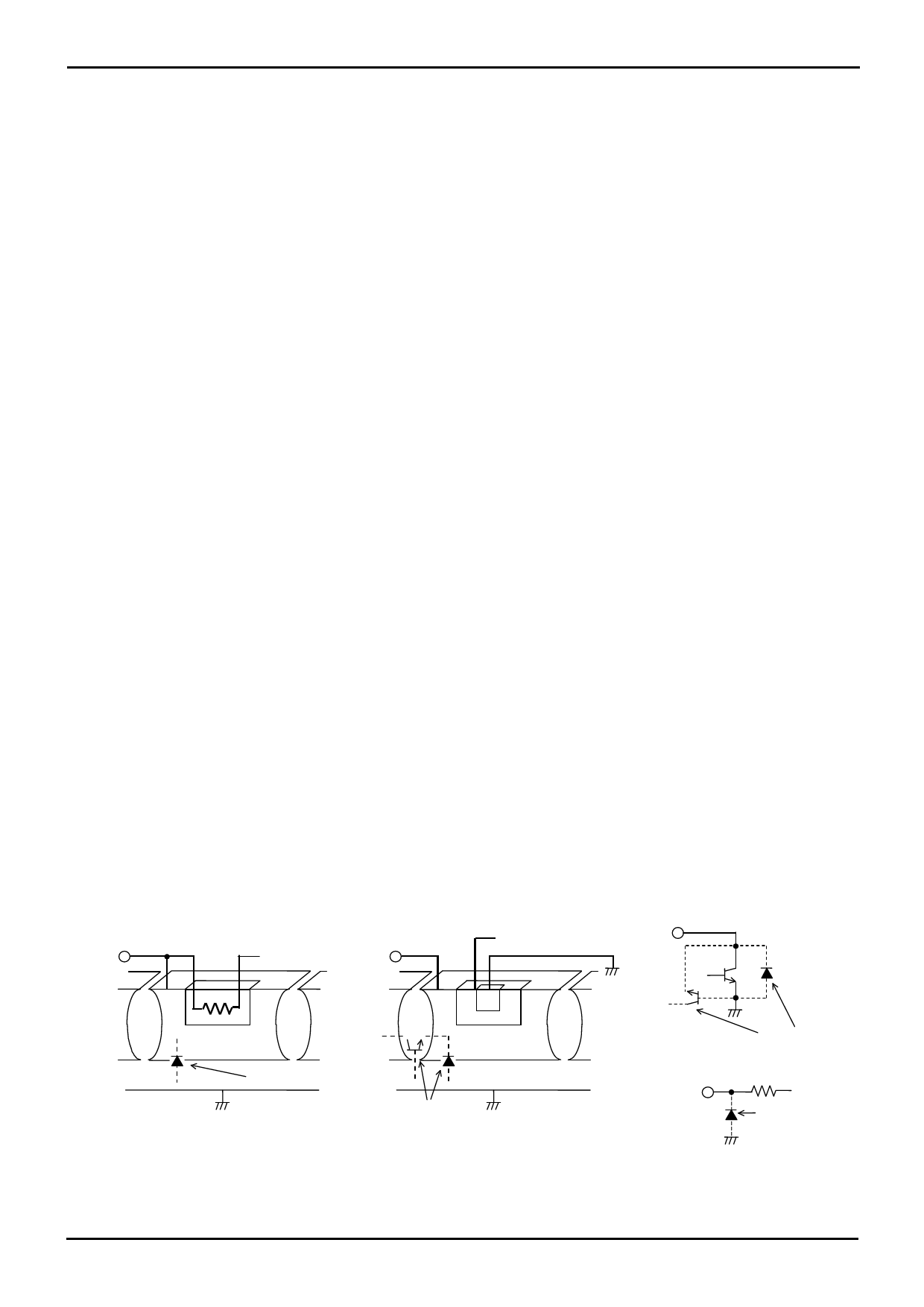
7) Regarding input pin of the IC
This monolithic IC contains P+ isolation and P substrate layers between adjacent elements in order to keep them isolated.
P-N junctions are formed at the intersection of these P layers with the N layers of other elements, creating a parasitic
diode or transistor. For example, the relation between each potential is as follows:
○When GND > Pin A and GND > Pin B, the P-N junction operates as a parasitic diode.
○When GND > Pin B, the P-N junction operates as a parasitic transistor.
Parasitic diodes can occur inevitable in the structure of the IC. The operation of parasitic diodes can result in mutual
interference among circuits, operational faults, or physical damage. Accordingly, methods by which parasitic diodes
operate, such as applying a voltage that is lower than the GND (P substrate) voltage to an input pin, should not be used.
(Pin A)
Resistor
(Pin B)
Transistor (NPN)
B
C
E
P+
N
P
P
N
P+
N
Parasitic element
GND
P+
N
P
N
P+
N
P substrate
Parasitic element
or transistor
GND
(Pin B)
BC
(Pin A)
E
GND
Parasitic element or
transistor
Parasitic element
Figure 18. Example of IC structure
www.rohm.com
© 2013 ROHM Co., Ltd. All rights reserved.
TSZ22111・15・001
10/15
TSZ02201-0T2T0AN00130-1-2
25.Apr.2013 Rev.002
Share Link: 