ML6554CU Ver la hoja de datos (PDF) - Fairchild Semiconductor
Número de pieza
componentes Descripción
Lista de partido
ML6554CU Datasheet PDF : 14 Pages
| |||
ML6554
PRODUCT SPECIFICATION
Functional Description
This switching regulator is capable of sinking and sourcing
3A of current without an external heatsink. The ML6554
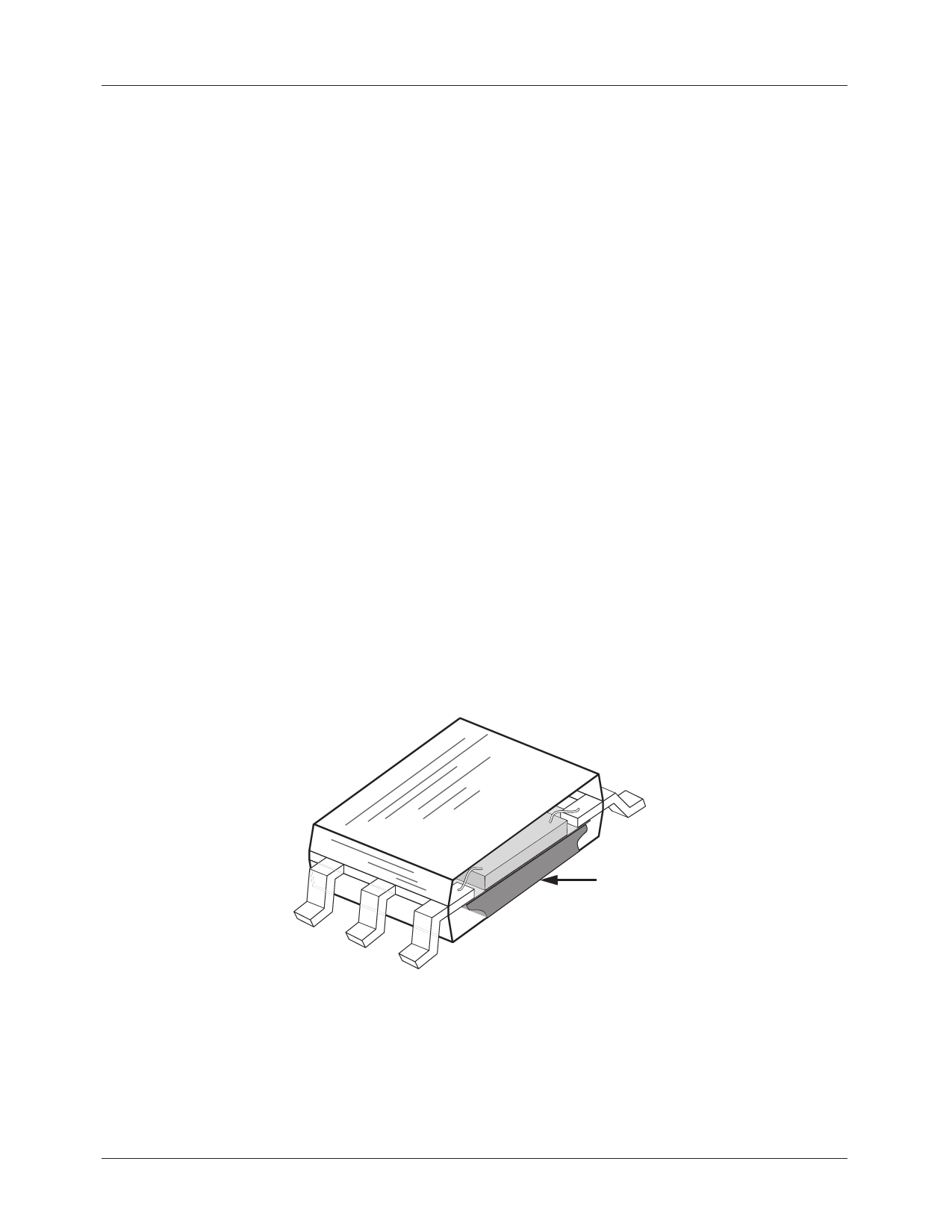
uses a power surface mount package (PSOP) that includes
an integrated heat slug. The heat can be piped through the
bottom of the device and onto the PCB (Figure 1).
The ML6554 integrates two power MOSFETs that can be
used to source and sink 3A of current while maintaining a
tight voltage regulation. Using the external feedback, the
output can be regulated well within 3% or less, depending on
the external components chosen. Separate voltage supply
inputs have been added to accommodate applications with
various power supplies for the databus and power buses, see
Figure 2.
Outputs
The output voltage pins (VL1, VL2) are tied to the databus,
address, or clock lines via an external inductor. See the
Applications section for recommendations. Output voltage
is determined by the VCCQ or VREFIN inputs.
Inputs
The input voltage pins (VCCQ or VREFIN) determine the
output voltages (VL1 or VL2) . In the default mode, where
the VREFIN pin is floating, the output voltage is 50% of the
VCCQ input. VCCQ can be the reference voltage for the
databus.
Output voltage can also be selected by forcing a voltage at
the VREFIN pin. In this case, the output voltage follows the
voltage at the VREFIN input. Simple voltage dividers can be
used this case to produce a wide variety of output voltages
between 0.7V and VDD–0.7V.
VREF Input and Output
The VREFIN input can be used to force a voltage at the
outputs (Inputs section, above). The VREFOUT pin is an
output pin that is driven by a small output buffer to provide
the VREF signal to other devices in the system. The output
buffer is capable of driving several output loads. The output
buffer can handle 3mA.
Other Supply Voltages
Several inputs are provide for the supply voltages: PVDD1,
PVDD2, AVCC, and VDD.
The PVDD1 and PVDD2 provide the power supply to the
power MOSFETs. VDD provides the voltage supply to the
digital sections, while AVCC supplies the voltage for the
analog sections. Again, see the Applications section for
recommendations.
Feedback Input
The VFB pin is an input that can be used for closed loop
compensation. This input is derived from the voltage output.
See application section for recommendation.
HEAT SLUG
Figure 1. Cutaway view of PSOP Package
4
REV. 1.1.3 3/8/02
Share Link: 