2961 Ver la hoja de datos (PDF) - Allegro MicroSystems
Número de pieza
componentes Descripción
Lista de partido
2961
Allegro MicroSystems

2961 Datasheet PDF : 12 Pages
| |||
2961
HIGH-CURRENT
HALF-BRIDGE
PRINTHEAD/MOTOR DRIVER
APPLICATIONS INFORMATION
The UDN2961B/W is a high current
half-bridge designed to drive a number of
inductive loads such as printer solenoids,
stepper motors, and dc motors. Load current
is sensed internally and is controlled by
pulse-width modulating (PWM) the output
driver(s) in a fixed off-time, variable-
frequency format. The peak current level is
set by the user’s selection of a reference
voltage. A slow current-decay mode
(chopping only the source driver) or a fast
current-decay mode (chopping both the
source and sink drivers) can be selected via
the MODE pin.
PWM CURRENT CONTROL
A logic low on the MODE pin sets the
current-control circuitry into the slow-decay
mode. The RS flip-flop is set initially, and
both the source driver and the sink driver are
turned ON when the INPUT pin is at a logic
low. As current in the load increases, it is
sensed by the internal sense resistor until the
sense voltage equals the trip voltage of the
comparator. At this time, the flip-flop is reset
and the source driver is turned OFF. Over the
range of VREF = 0.8 V to 3.4 V, the output
current trip point transfer function is a direct
linear function of the reference voltage:
ITRIP = VREF
To ensure an accurate chop current level
(±10%), an external 2940 Ω ±1% resistor
(RCV) is used. The actual load current peak
will be slightly higher than the trip point
(especially for low-inductance loads) because
of the internal logic and switching delays
(typically 1.5 µs). After the source driver turns
OFF, the load current decays, circulating
through an external ground clamp diode, the
load, and the sink transistor. The source
driver’s OFF time (and therefore the magni-
tude of the current decrease) is determined
by the one-shot’s external RC timing compo-
nents:
tOFF = RC
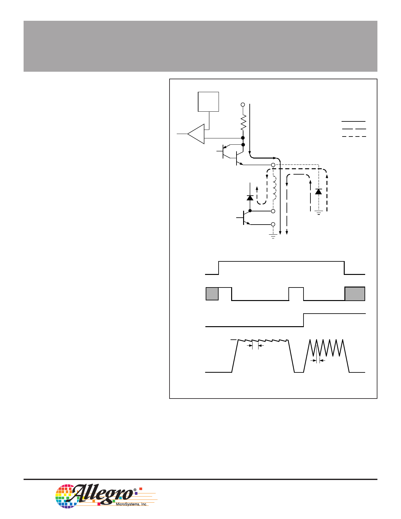
REF
CIRCUIT
V
BB
DRIVE CURRENT
+
-
V SENSE
RECIRCULATION (SLOW-DECAY MODE)
RECIRCULATION (FAST-DECAY MODE)
VBB
Dwg. EP-037
ENABLE
INPUT
MODE
ITRIP
RC
LOAD
CURRENT
RC/2
Dwg. WP-015
within the range of 20 kΩ to 100 kΩ and 100 pF to 1000 pF. When the
one-shot times out, the flip-flop is set again, the source driver is re-
enabled, and the load current again is allowed to rise to the set peak
value and trip the comparator. This cycle repeats itself, maintaining the
average load current at the desired level.
115 Northeast Cutoff, Box 15036
Worcester, Massachusetts 01615-0036 (508) 853-5000
Share Link: