IRF420 Ver la hoja de datos (PDF) - Intersil
Número de pieza
componentes Descripción
Lista de partido
IRF420 Datasheet PDF : 7 Pages
| |||
IRF420, IRF421, IRF422, IRF423
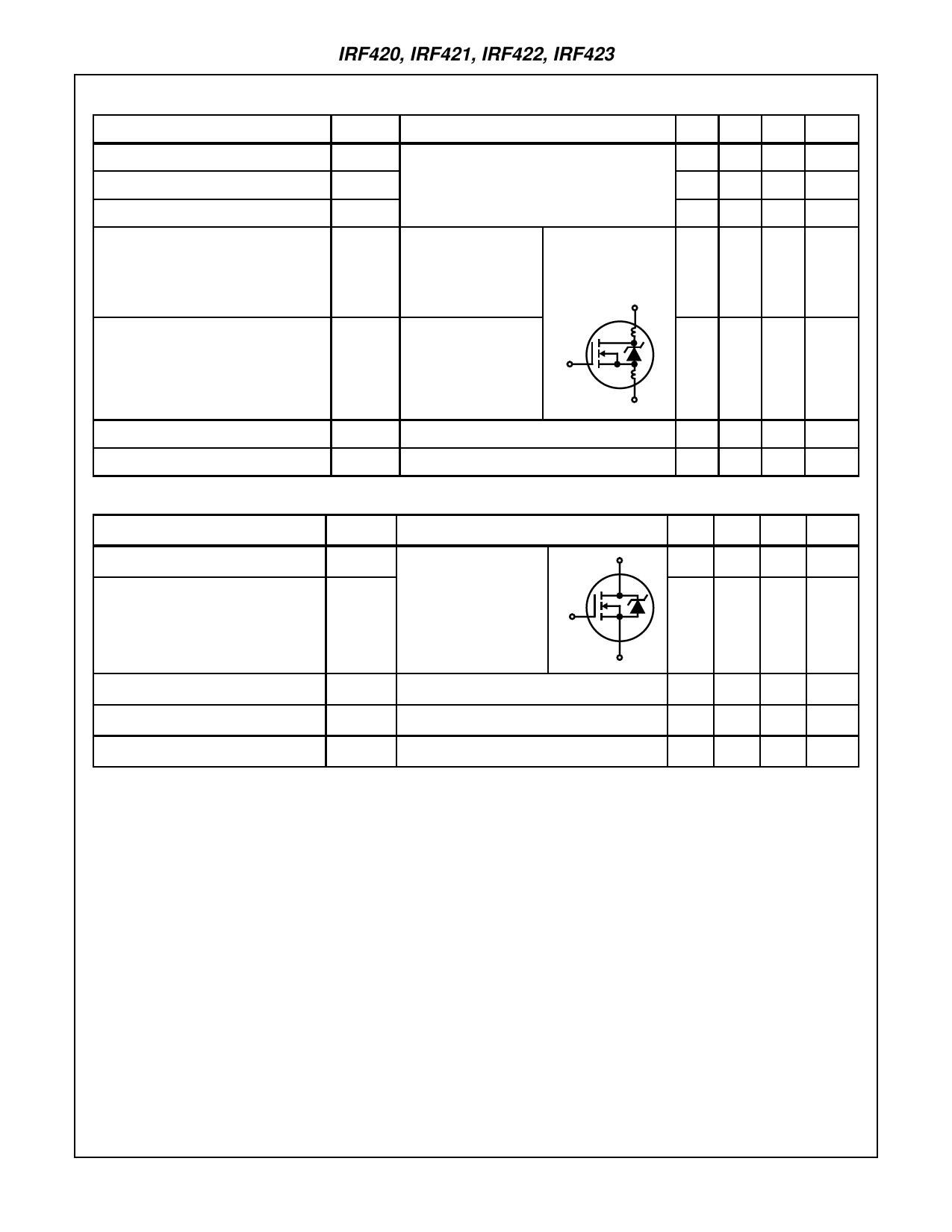
Electrical Specifications TC = 25oC, Unless Otherwise Specified (Continued)
PARAMETER
SYMBOL
TEST CONDITIONS
Input Capacitance
Output Capacitance
Reverse Transfer Capacitance
Internal Drain Inductance
Internal Source Inductance
CISS
COSS
CRSS
LD
LS
VDS = 25V, VGS = 0V, f = 1MHz, (Figure 11)
Measured between the
Contact Screw on the
Flange that is Closer to
Source and Gate Pins
and the Center of Die.
Modified MOSFET
Symbol Showing the
Internal Devices
Inductances.
D
Measured from the
Source Lead, 6mm
(0.25in) from the Flange
G
and Source Bonding
Pad.
LD
LS
S
MIN TYP MAX UNITS
- 300 -
pF
-
75
-
pF
-
20
-
pF
-
5.0
-
nH
- 12.5 -
nH
Thermal Resistance Junction to Case
Thermal Resistance Junction to Ambient
RθJC
RθJA
Free Air Operation
-
-
2.5 oC/W
-
-
30 oC/W
Source to Drain Diode Specifications
PARAMETER
SYMBOL
TEST CONDITIONS
MIN TYP MAX UNITS
Continuous Source to Drain Current
Pulse Source to Drain Current
(Note 3)
ISD
Modified MOSFET
Symbol Showing the
ISDM Integral Reverse P-N
Junction Diode
G
D
-
-
2.5
A
-
-
10
A
S
Source to Drain Diode Voltage (Note 2)
VSD
TJ = 25oC, ISD = 2.5A, VGS = 0V, (Figure 13)
-
-
1.4
V
Reverse Recovery Time
trr
TJ = 25oC, ISD = 2.5A, dISD/dt = 100A/µs
130 270 540
ns
Reverse Recovered Charge
QRR
TJ = 25oC, ISD = 2.5A, dISD/dt = 100A/µs
0.57 1.2 2.3
µC
NOTES:
2. Pulse test: pulse width ≤ 300µs, duty cycle ≤ 2%.
3. Repetitive rating: pulse width limited by max junction temperature. See Transient Thermal Impedance curve (Figure 3).
4. VDD = 50V, starting TJ = 25oC, L = 60mH, RG = 25Ω, peak IAS = 2.5A, Figures 15, 16.
5-3
Share Link: 