74LV251 Ver la hoja de datos (PDF) - Philips Electronics
Número de pieza
componentes Descripción
Lista de partido
74LV251 Datasheet PDF : 12 Pages
| |||
Philips Semiconductors
8-input multiplexer (3-State)
Product specification
74LV251
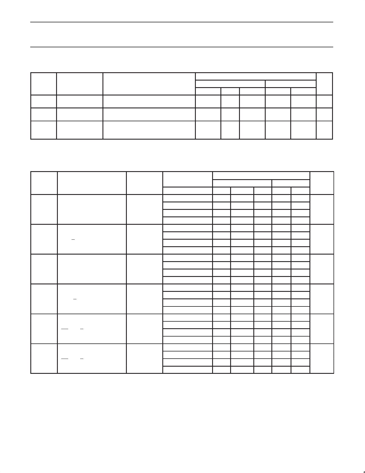
DC ELECTRICAL CHARACTERISTICS (Continued)
SYMBOL PARAMETER
TEST CONDITIONS
II
Input leakage
current
VCC = 3.6 V; VI = VCC or GND
ICC
Quiescent supply
current; MSI
VCC = 3.6 V; VI = VCC or GND; IO = 0
∆ICC
Additional
quiescent supply
current per input
VCC = 2.7 V to 3.6 V; VI = VCC – 0.6 V
NOTE:
1. All typical values are measured at Tamb = 25°C.
LIMITS
-40°C to +85°C
MIN
TYP1 MAX
1.0
-40°C to +125°C
MIN
MAX
1.0
UNIT
µA
20.0
160
µA
500
850
µA
AC CHARACTERISTICS
GND = 0V; tr = tf = 2.5ns; CL = 50pF; RL = 1KΩ
SYMBOL
PARAMETER
WAVEFORM
CONDITION
VCC(V)
1.2
tPHL/tPLH
Propagation delay
In to Y
2.0
Figure 1
2.7
3.0 to 3.6
1.2
tPHL/tPLH
Propagation delay
In to Y
2.0
Figure 2
2.7
3.0 to 3.6
1.2
tPHL/tPLH
Propagation delay
Sn to Y
2.0
Figure 1
2.7
3.0 to 3.6
1.2
tPHL/tPLH
Propagation delay
Sn to Y
2.0
Figure 2
2.7
3.0 to 3.6
1.2
tPZH/tPZL
3-State output disable time
OE to Y, Y
Figure 2
2.0
2.7
3.0 to 3.6
1.2
tPHZ/tPLZ
3-State output disable time
OE to Y, Y
Figure 2
2.0
2.7
3.0 to 3.6
NOTES:
1. Unless otherwise stated, all typical values are measured at Tamb = 25°C
2. Typical values are measured at VCC = 3.3 V.
LIMITS
–40 to +85 °C
MIN TYP1 MAX
90
31
58
23
43
172
34
100
34
65
25
48
192
38
120
41
77
30
56
232
45
125
43
82
31
60
242
48
65
22
43
16
31
122
25
60
22
39
17
29
132
24
–40 to +125 °C
MIN MAX
70
51
41
77
56
45
92
68
54
97
71
57
51
38
30
48
36
29
UNIT
ns
ns
ns
ns
ns
ns
1998 May 20
6
Share Link: 