A49LF040ATL-33 Ver la hoja de datos (PDF) - AMIC Technology
Número de pieza
componentes Descripción
Lista de partido
A49LF040ATL-33 Datasheet PDF : 32 Pages
| |||
A49LF040A
Table 18: LPC Mode Interface AC Input/Output Characteristics
Symbol Parameter
Test Conditions
IOH (AC) Switching Current High
0 < VOUT ≤ 0.3VDD
0.3VDD < VOUT ≤ 0.9VDD
0.7VDD < VOUT ≤ VDD
(Test Point)
VOUT = 0.7VDD
IOL (AC) Switching Current Low
VDD > VOUT ≥ 0.6VDD
0.6VDD > VOUT > 0.1VDD
0.18VDD > VOUT > 0
(Test Point)
VOUT=0.18VDD
ICL
Low Clamp Current
-3 < VIN ≤ -1
ICH
High Clamp Current
VDD+4 > VIN > VDD+1
slewr Output Rise Slew Rate
0.2VDD-0.6VDD load
slewf Output Fall Slew Rate
0.6VDD-0.2VDD load
Notes:
1. See PCI specification.
2. PCI specification output load is used.
Min
-12 VDD
-17.1(VDD-VOUT)
16VDD
26.7VOUT
-25+(VIN+1)/0.015
25+(VIN-VDD-1)/0.015
1
1
Max
Equation C
-32 VDD
Equation D
38VDD
4
4
Units
mA
mA
mA
mA
mA
mA
mA
mA
mA
mA
V/ns
V/ns
Table 19: LPC Mode Interface Reset Timing Parameters, VDD=3.0-3.6V
Symbol Parameter
Min
Max
TPRST
TKRST
TRSTP
TRSTF
TRST(1)
TRSTE
VDD Stable to Reset Low
Clock Stable to Reset Low
RST Pulse Width
RST Low to Output Float
RST High to LFRAME Low
RST Low to Reset During Erase or Program
RST or INIT Slew Rate
1
100
100
48
1
10
50
Notes:
1. There will be a latency of TRSTE if a reset procedure is performed during a Program or Erase operation.
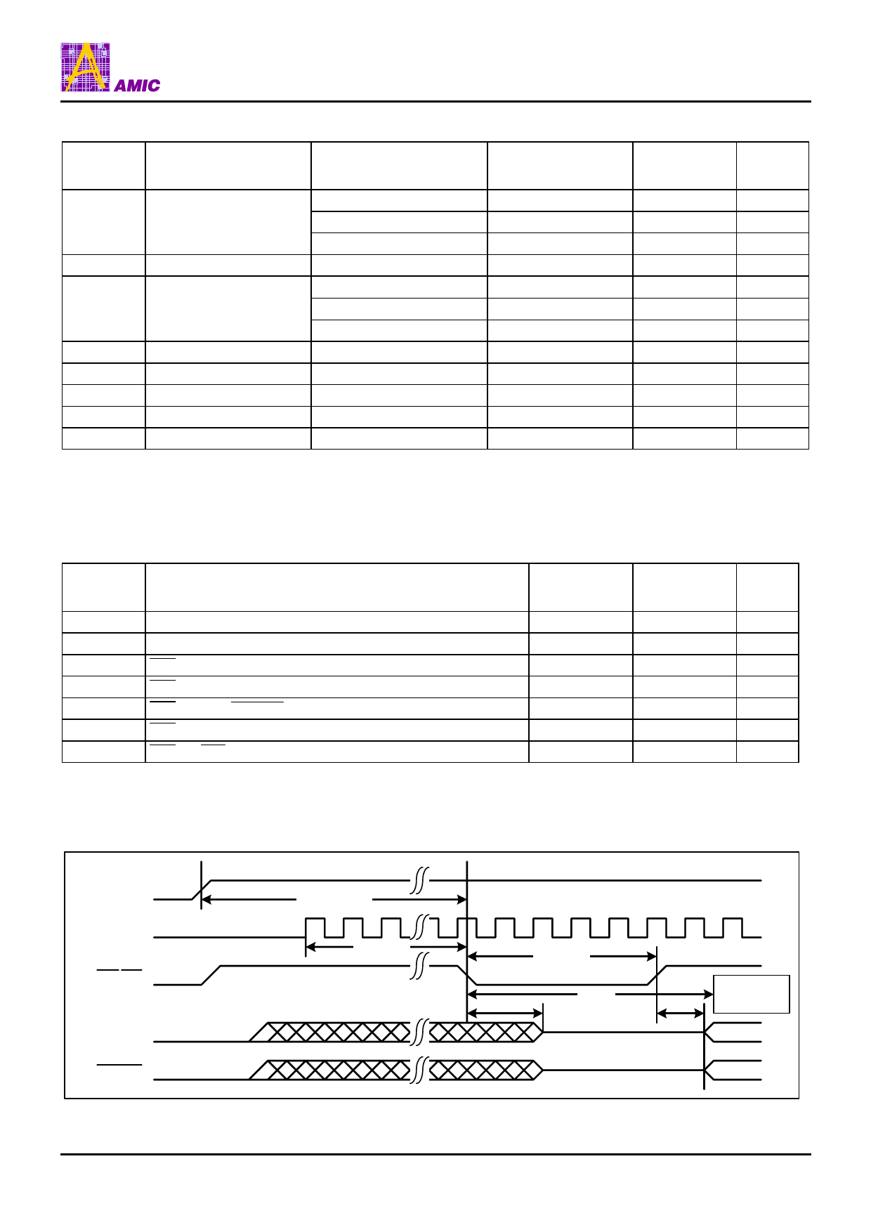
Figure 7: Reset Timing Diagram
Units
ms
µs
ns
ns
µs
µs
mV/ns
VDD
LCLK
RST/INIT
LAD[3:0]
LFRAME
TPRST
TKRST
TRSTF
TRSTP
TRSTE
TRST
Program or Erase
Operation Aborted
PRELIMINARY (March, 2006, Version 0.1)
18
AMIC Technology, Corp.
Share Link: 