ADF4193(RevB) Ver la hoja de datos (PDF) - Analog Devices
Número de pieza
componentes Descripción
Lista de partido
ADF4193 Datasheet PDF : 28 Pages
| |||
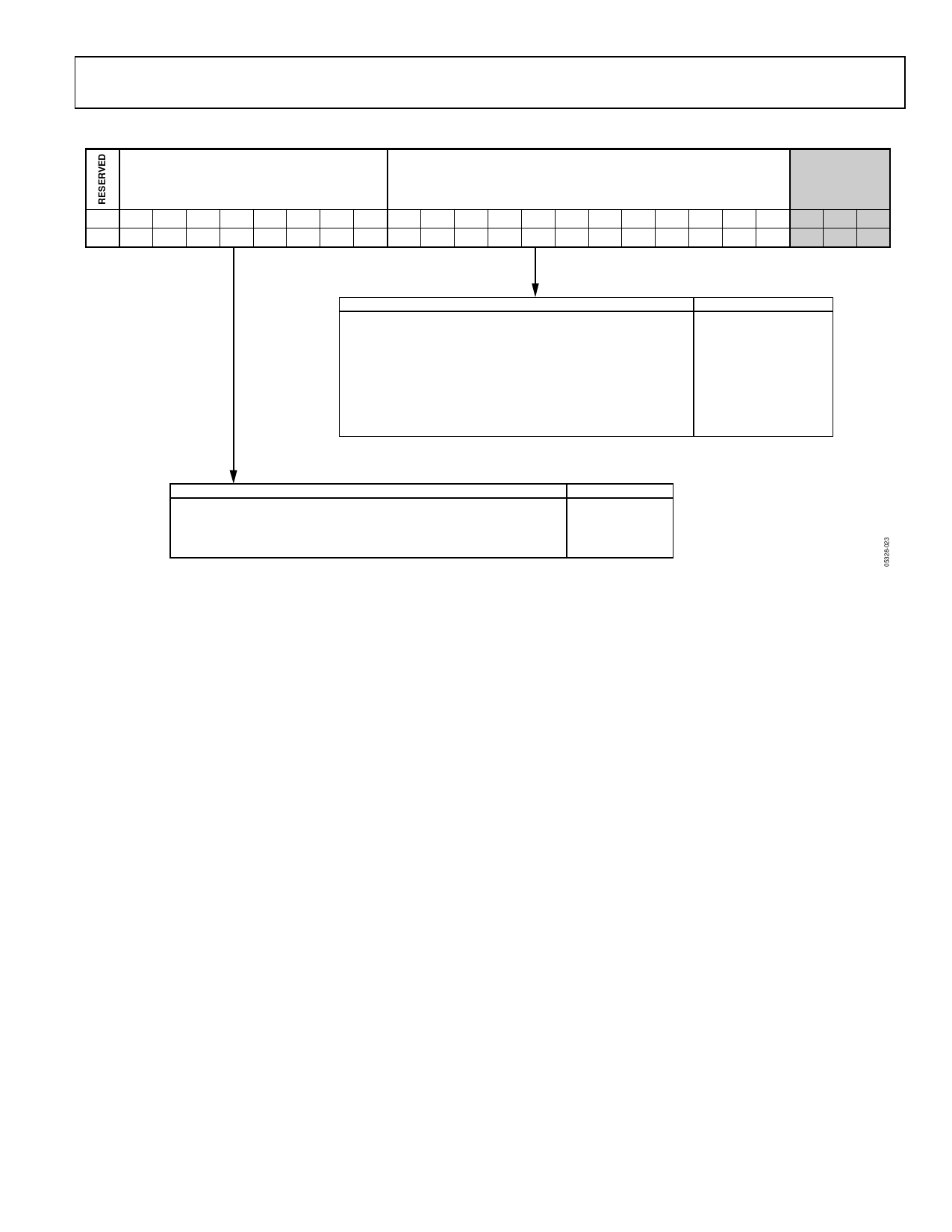
ADF4193
FRAC/INT REGISTER (R0)
8-BIT RF INT VALUE
12-BIT RF FRAC VALUE
CONTROL
BITS
DB23 DB22 DB21 DB20 DB19 DB18 DB17 DB16 DB15 DB14 DB13 DB12 DB11 DB10 DB9
0
N8 N7 N6 N5 N4 N3 N2 N1 F12 F11 F10 F9 F8 F7
DB8
F6
DB7
F5
DB6
F4
DB5
F3
DB4
F2
DB3 DB2 DB1 DB0
F1 C3 (0) C2 (0) C1 (0)
F12
F11
F10
F3
F2
F1
FRACTIONAL VALUE (FRAC)
0
0
0
..........
0
0
0
0
0
0
0
..........
0
0
1
1
0
0
0
..........
0
1
0
2
0
0
0
..........
0
1
1
3
.
.
.
..........
.
.
.
.
.
.
.
..........
.
.
.
.
.
.
.
..........
.
.
.
.
1
1
1
..........
1
0
0
4092
1
1
1
..........
1
0
1
4093
1
1
1
..........
1
1
0
4094
1
1
1
..........
1
1
1
4095
0 = < FRAC < MOD
N8
N7
N6
N5
N4
N3
N2
N1
0
0
0
1
1
0
1
0
.
.
.
.
.
.
.
.
.
.
.
.
.
.
.
.
.
.
.
.
.
.
.
.
1
1
1
1
1
1
1
1
INTEGER VALUE (INT)
26
.
.
.
255
Figure 29. FRAC/INT Register (R0)
R0, the FRAC/INT register, is used to program the synthesizer
output frequency. On the next PFD cycle following a write to
R0, the N divider section is updated with the new INT and
FRAC values. At the same time, the PLL automatically enters
fast lock mode and the charge pump current is increased to its
maximum value and stays at this value until the ICP timeout
counter times out, and switches SW1, SW2, and SW3 closed
and remains closed until the SW1, SW2, and SW3 timeout
counters time out.
Once all registers are programmed during the initialization
sequence (see Table 8), all that is required thereafter to program
a new channel is a write to R0. However, as described in the
Programming section, it can also be desirable to program R1
and R2 register settings on a channel-by-channel basis. These
settings are double buffered by the write to R0. This means that
while the data is loaded through the serial interface on the
respective R1 and R2 write cycles, the synthesizer is not updated
with their data until the next write to Register R0.
Control Bits
The three LSBs, Control Bit C3, Control Bit C2, and Control Bit C1,
should be set to 0, 0, 0, respectively, to select R0, the FRAC/INT
register.
Reserved Bit
Bit DB23 is reserved and must be set to 0.
8-Bit INT Value
These eight bits set the INT value, which determines the integer
part of the feedback division factor. All integer values from 26
to 255 are allowed. See the Worked Example section.
12-Bit FRAC Value
The 12 FRAC bits set the numerator of the fraction that is input
to the Σ-Δ modulator. This, along with INT, specifies the new
frequency channel that the synthesizer locks to, as shown in the
Worked Example section. FRAC values from 0 to MOD − 1
cover channels over a frequency range equal to the PFD
reference frequency.
Rev. B | Page 15 of 28
Share Link: 