AS8201 Ver la hoja de datos (PDF) - austriamicrosystems AG
Número de pieza
componentes Descripción
Lista de partido
AS8201 Datasheet PDF : 13 Pages
| |||
TTP/C-C1 Communications Controller Data Sheet
AS8201
Austria Mikro Systeme International AG
AC Characteristics
Clock applied at XOUT0, resp. XOUT1.
PARAMETER
data in setup
time
data output
valid
SYMBOL
tsetup
tdav
PIN
all IN,
all IO
all OUT,
all IO
MIN
20 ns
MAX
35 ns
NOTE
vs. Falling edge of clk @XOUT0, XOUT1
vs. rising edge of clk @ XOUT0, XOUT1
Application Information
ROM Interface
Pin name
ROM_DATA
ROM_ADDRESS
ROM_CEB
ROM_WEB
ROM_OEB
ROM_READY
ROM_RESETB
mode
inout (tri)
out
out
out
out
in
out
width
16
17
1
1
1
1
1
comment
ROM data bus
ROM address bus
ROM chip enable
ROM write enable
ROM output enable
ROM ready
external reset line
Table 1 ROM Interface Ports
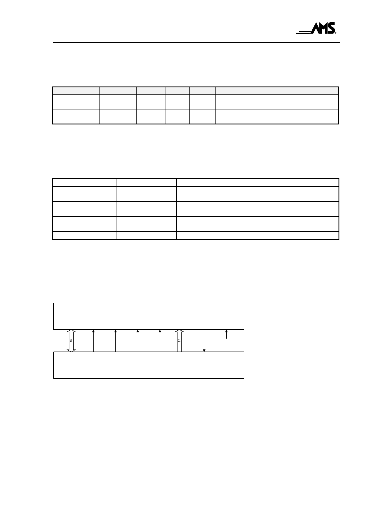
The timing and behaviour of the ROM Interface is designed to operate with the AM29F200
Flash EPROM or compatible devices. For detailed timing information see [AM29F200] 1. Figure
2 shows the connection between TTP/C-C1 controller and the AM29F200 Flash. The contents
of the Flash memory is loaded into the instruction memory by a boot sequencer automatically
after power on.
DQ0-DQ15
RESET
AM29F200
WE
CE
OE
A0-A16
RY/BY
BYTE
VCC
rom_data
rom_resetb rom_web
rom_ceb
rom_oeb rom_address
TTA-C1
rom_ready
Figure 2 ROM Interface2
Host CPU Interface
The host CPU interface also referred as CNI (controller network interface) connects the
application circuitry to the TTP/C network. As shown in Table 2 all RAM_-lines provide
asynchronous read/write access to a dual ported RAM. There are no setup/hold constraints
referred to the microtick (main clock “clk”). The signals have to be applied for certain duration
according to Table 3. So, the applied signals get synchronised with the microtick. The TIME_-
1 [AMD96] Advanced Micro Devices, "Flash Memory Products - 1996 Data Book/Handbook", Advanced Micro Devices Inc., 1996.
2 The label TTA-C1 stands for TTP/C-C1 in the following diagrams
Rev. NC, October 1999
Page 7 of 13
Share Link: 