PDI1394P11 Ver la hoja de datos (PDF) - Philips Electronics
Número de pieza
componentes Descripción
Lista de partido
PDI1394P11 Datasheet PDF : 20 Pages
| |||
Philips Semiconductors
3-port physical layer interface
Product specification
PDI1394P11
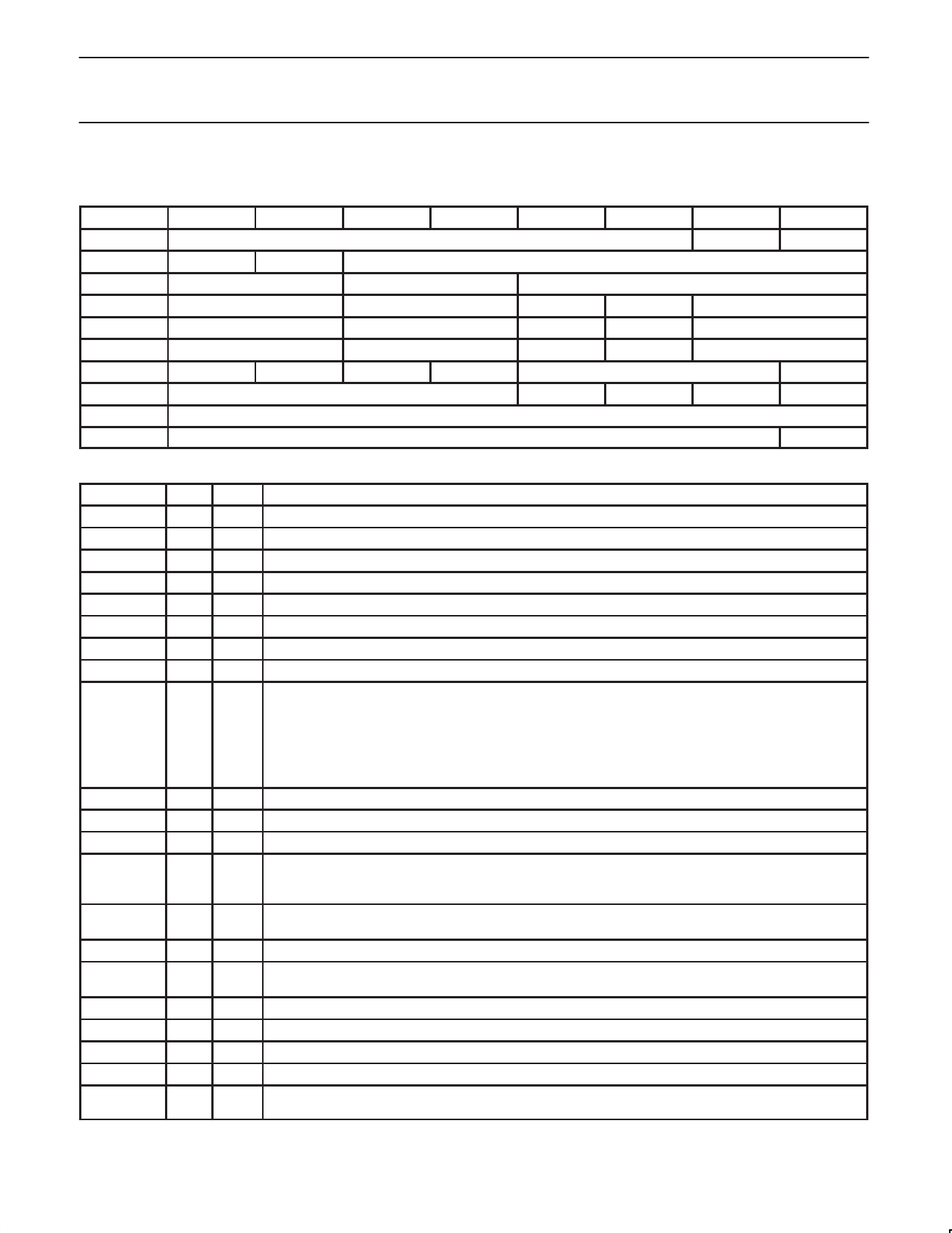
16.0 INTERNAL REGISTER CONFIGURATION
The accessible internal registers of this device are listed in the following tables:
ADDRESS
0
1
2
3
4
0000
Physical ID
0001
RHB
IBR
0010
SPD
Reserved
0011
AStat1
BSTAT1
Ch1
0100
AStat2
BSTAT2
Ch2
0101
AStat3
BSTAT3
Ch3
0110
Loopint
CPSint
CPS
IR
0111
Reserved
PC2
1000
Reserved
1001
Reserved
5
GC
NP
Con1
Con2
Con3
Reserved
PC1
6
7
R
CPS
Reserved
Reserved
Reserved
C
PC0
C
ISBR
The keys are listed as follows:
FIELD
SIZE TYPE
DESCRIPTION
Physical ID 6
Rd
The address of the local node determined during the Self-ID.
R
1
Rd
Indicates that the local node is the root.
CPS
1
Rd
Cable power Status (CPS input).
RHB
1
Rd/Wr Root hold-OFF bit. Instructs the local node to try to become the root during the next bus reset.
IBR
1
Rd/Wr Initiate Bus Reset. Instructs the PDI1394P11 to initiate Bus Reset at the next opportunity.
GC
6
Rd/Wr Gap count. Used to optimize the gap times based on the size of the network. See 1394 standard for details.
SPD
2
Rd
Indicates the top signaling speed of the local ports.
NP
4
Rd
The number of ports on this device, set to 0011.
AStat(n)
2
Rd
The line state of TPA of port n:
11 = Z
01 = 1
10 = 0
00 = invalid data state. Power up reset initializes to this line state. Also this line state is output during
transmit and receive operations. The line state outputs are generally valid during arbitration and idle
conditions on the bus.
BStat(n)
2
Rd
The line state of TPB of port n. The encoding is the same as AStat(n).
Ch(n)
1
Rd
If = 1, then port n is a child, otherwise it is a parent.
Con(n)
2
Rd
If = 1, then port n is connected, otherwise it is disconnected.
Loopint
1
Rd/Wr Indicates that the PDI1394P11 times out in tree ID, waiting for child signal from two or more ports. The
Loopint can be cleared by writing a ‘‘0’’ to this bit, but if the loop configuration has not been corrected, it will
promptly return to a ‘‘1’’.
CPSint
1
Rd/Wr Indicates that the cable power has dropped too low for guaranteed reliable operation. It can be cleared by
writing a ‘‘0’’ to the bit, but it will immediately return if CPS is still LOW.
CPS
1
Rd/Wr Cable Power Status is also included in this register to expedite handling the CPSint.
IR
1
Rd/Wr Indicates that the last bus reset was initiated in the PDI1394P11. This bit is also included in the self ID
packet.
C
1
Rd
If set, this node is a contender for the role of bus or Isochronous Resource Manager.
PC2
1
Rd
The least significant power class bit
PC1
1
Rd
The middle power class bit
PC0
1
Rd
The most significant power class bit
ISBR
1
Rd/Wr Initiate Short Bus Reset. Instructs the PDI1394P11 to initiate an arbitrated short bus reset.
See Section 17.1.
1999 Apr 09
9
Share Link: 