CM1200E4C-34N Ver la hoja de datos (PDF) - Mitsumi
Número de pieza
componentes Descripción
Lista de partido
CM1200E4C-34N Datasheet PDF : 6 Pages
| |||
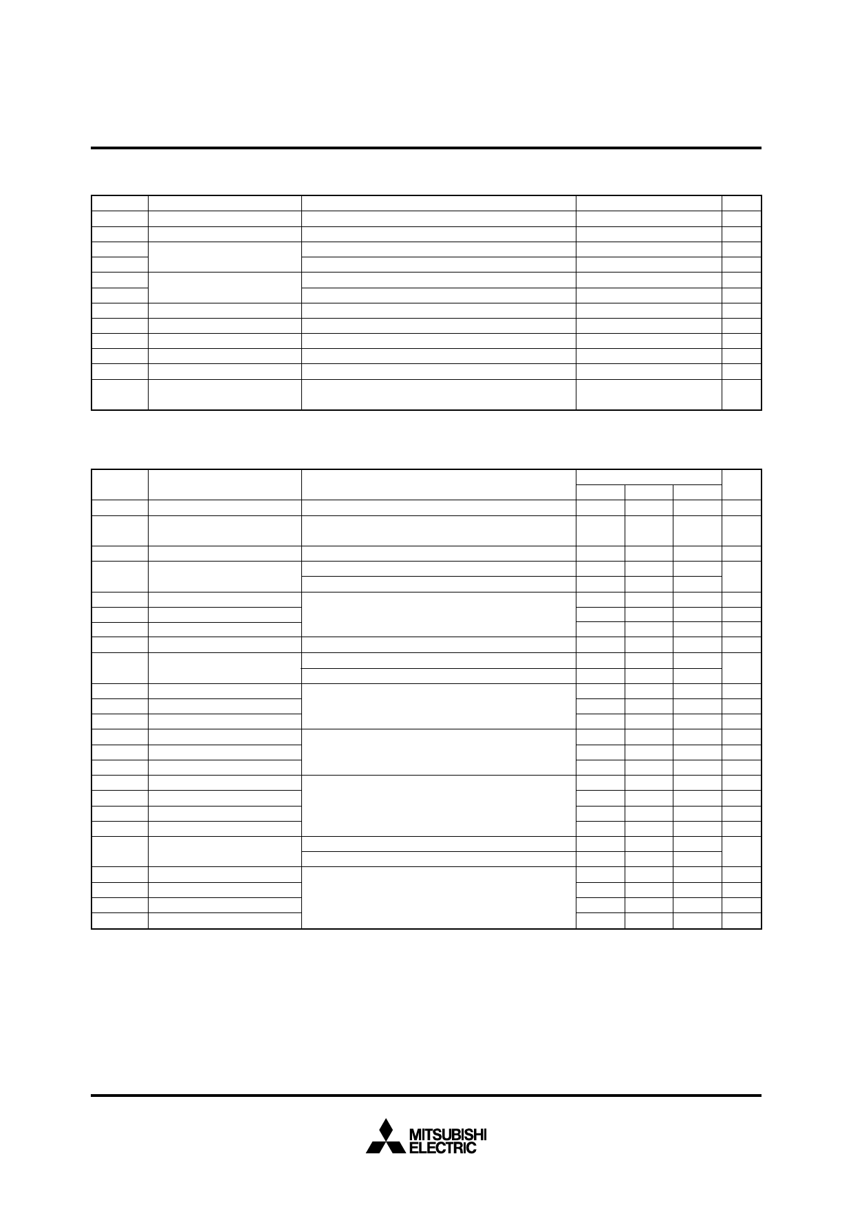
4th-Version HVIGBT (High Voltage Insulated Gate Bipolar Transistor) Modules
MITSUBISHI HVIGBT MODULES
CM1200E4C-34N
HIGH POWER SWITCHING USE
INSULATED TYPE
MAXIMUM RATINGS
Symbol
Item
Conditions
Ratings
Unit
VCES
Collector-emitter voltage
VGE = 0V, Tj = 25°C
1700
V
VGES
Gate-emitter voltage
VCE = 0V, Tj = 25°C
±20
V
IC
Collector current
ICM
TC = 75°C
Pulse
1200
A
(Note 1)
2400
A
IE (Note 2) Emitter current
IEM (Note 2)
Pulse
1200
A
(Note 1)
2400
A
PC (Note 3) Maximum power dissipation TC = 25°C, IGBT part
6500
W
Tj
Junction temperature
–40 ~ +150
°C
Top
Operating temperature
–40 ~ +125
°C
Tstg
Storage temperature
–40 ~ +125
°C
Viso
Isolation voltage
RMS, sinusoidal, f = 60Hz, t = 1min.
4000
V
Maximum short circuit pulse VCC = 1200V, VCES ≤ 1700V, VGE = 15V
tpsc
width
Tj = 125°C
10
µs
ELECTRICAL CHARACTERISTICS
Symbol
Item
ICES
VGE(th)
Collector cut-off current
Gate-emitter
threshold voltage
Conditions
VCE = VCES, VGE = 0V, Tj = 25°C
IC = 120mA, VCE = 10V, Tj = 25°C
Limits
Min
Typ
—
—
6.0
7.0
IGES
Gate leakage current
VGE = VGES, VCE = 0V, Tj = 25°C
—
VCE(sat)
Collector-emitter
saturation voltage
IC = 1200A, VGE = 15V, Tj = 25°C
IC = 1200A, VGE = 15V, Tj = 125°C
(Note 4) —
(Note 4) —
Cies
Input capacitance
—
Coes
Cres
Output capacitance
VCE = 10V, f = 100kHz
Reverse transfer capacitance VGE = 0V, Tj = 25°C
—
—
Qg
Total gate charge
VCC = 850V, IC = 1200A, VGE = 15V, Tj = 25°C
—
VEC (Note 2) Emitter-collector voltage
IE = 1200A, VGE = 0V, Tj = 25°C
IE = 1200A, VGE = 0V, Tj = 125°C
(Note 4) —
(Note 4) —
td(on)
Turn-on delay time
VCC = 850V, IC = 1200A, VGE = ±15V
—
tr
Turn-on rise time
RG(on) = 0.6Ω, Tj = 125°C, Ls = 150nH
—
Eon
Turn-on switching energy
Inductive load
—
td(off)
Turn-off delay time
VCC = 850V, IC = 1200A, VGE = ±15V
—
tf
Turn-off fall time
RG(off) = 3.3Ω, Tj = 125°C, Ls = 150nH
—
Eoff
Turn-off switching energy
Inductive load
—
trr (Note 2)
Irr (Note 2)
Qrr (Note 2)
Reverse recovery time
Reverse recovery current
Reverse recovery charge
VCC = 850V, IC = 1200A, VGE = ±15V
RG(on) = 0.6Ω, Tj = 125°C, Ls = 150nH
Inductive load
—
—
—
Erec (Note 2) Reverse recovery energy
—
VF (Note 5) Forward voltage
IE = 1200A, VGE = 0V, Tj = 25°C
IE = 1200A, VGE = 0V, Tj = 125°C
(Note 4) —
(Note 4) —
trr (Note 5)
Irr (Note 5)
Qrr (Note 5)
Erec (Note 5)
Reverse recovery time
Reverse recovery current
Reverse recovery charge
Reverse recovery energy
VCC = 850V, IC = 1200A, VGE = ±15V
di/dt = 2900A/µs, Tj = 125°C, Ls = 150nH
Inductive load
—
—
—
—
—
2.15
2.40
176
9.6
2.8
6.8
2.60
2.30
1.00
0.40
380
1.20
0.30
360
1.00
560
300
220
2.60
2.30
1.00
560
300
220
Note 1. Pulse width and repetition rate should be such that junction temperature (Tj) does not exceed Topmax rating (125°C).
2. The symbols represent characteristics of the anti-parallel, emitter to collector free-wheel diode (FWDi).
3. Junction temperature (Tj) should not exceed Tjmax rating (150°C).
4. Pulse width and repetition rate should be such as to cause negligible temperature rise.
5. The symbols represent characteristics of the clamp diode (Clamp-Di).
Unit
Max
4 mA
8.0
V
0.5 µA
2.80
V
—
—
nF
—
nF
—
nF
—
µC
3.30
V
—
—
µs
—
µs
— mJ/pulse
—
µs
—
µs
— mJ/pulse
—
µs
—
A
—
µC
— mJ/pulse
3.30
V
—
—
µs
—
A
—
µC
— mJ/pulse
HVIGBT (High Voltage Insulated Gate Bipolar Transistor) Modules
Jul. 2005
Share Link: 