CS8920A Ver la hoja de datos (PDF) - Cirrus Logic
Número de pieza
componentes Descripción
Lista de partido
CS8920A Datasheet PDF : 144 Pages
| |||
CS8920A
out value terminates initialization from the
EEPROM. If an EEPROM is attached but not
used for configuration, Crystal recommends that
the high byte of the first word be programmed
with 00h in order to ensure that the CS8920A
will not attempt to read configuration data from
the EEPROM.
Setting Plug And Play Support Enabled/dis-
abled: Setting bit four of the high byte of the
header disables the CS8920A’s Plug and Play
support. Clearing this bit leaves Plug and Play
support enabled (default). For example, a value
of 1011-XXXX (X = do not care) for the high
byte disables Plug and Play support while a
value of 1010-XXXX leaves Plug and Play en-
abled.
Determining Number of Bytes in the Reset
Configuration Block: The low byte of the Reset
Configuration Block header is known as the link
byte. The value of the Link Byte represents the
number of bytes of configuration data in the Re-
set Configuration Block. The two bytes used for
the header are excluded when calculating the
Link Byte value.
For example, a Reset Configuration Block
header of A112h indicates a non-sequential
EEPROM programmed with eighteen (12h)
bytes of configuration data. The CS8920A’s
Plug and Play support is enabled. The Reset
Configuration Block occupies twenty bytes (10
words) of EEPROM space (2 bytes for the
header and 18 bytes of configuration data).
Groups of Configuration Data
Configuration data are arranged as groups of
words. Each group contains one or more words
of data that are to be loaded into PacketPage reg-
isters. The first word of each group is referred to
as the Group Header. The Group Header indi-
cates the number of words in the group and the
address of the PacketPage register into which the
first data word in the group is to be loaded. Any
DS238PP2
remaining words in the group are stored in suc-
cessive PacketPage registers.
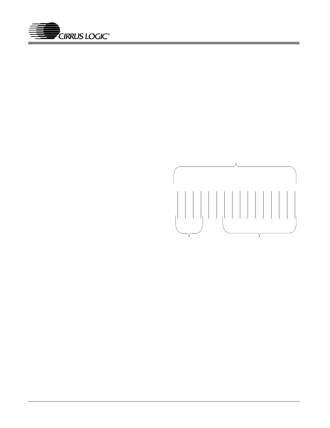
Group Header: Bits F through C of the Group
Header specify the number of words in each
group that are to be transferred to PacketPage
registers (see Figure 3.1). This value is two less
than the total number of words in the group, in-
cluding the Group Header. For example, if bits F
through C contain 0001, there are three words in
the group (a Group Header and two words of
configuration data).
First Word of a Group of Words
FEDCBA9 8 7 6 5 4 3 2 1 0
00
Number of Words
10-bit PacketPage Address
in Group
Figure 3.1. Group Header
Bits 9 through 0 of the Group Header specify a
10-bit PacketPage Address. This address defines
the PacketPage register that will be loaded with
the first word of configuration data from the
group. Bits B and A of the Group Header are
forced to 0, restricting the destination address
range to the first 1024 bytes of PacketPage mem-
ory.
Figure 3.1 shows the format of the Group
header.
Reset Configuration Block Checksum
A checksum is stored in the high byte position
of the word immediately following the last group
of data in the Reset Configuration Block. (The
21
Share Link: 