HFA3763 Ver la hoja de datos (PDF) - Intersil
Número de pieza
componentes Descripción
Lista de partido
HFA3763 Datasheet PDF : 10 Pages
| |||
HFA3763
Absolute Maximum Ratings TA = 25oC
Supply Voltage . . . . . . . . . . . . . . . . . . . . . . . . . . . . . . -0.3V to +6.0V
Voltage on Any Other Pin. . . . . . . . . . . . . . . . . . -0.3V to VCC +0.3V
Operating Conditions
Supply Voltage Range . . . . . . . . . . . . . . . . . . . . . . . . +2.7V to +5.5V
Operating Temperature Range . . . . . . . . . . . . . . -40oC ≤ TA ≤ 85oC
Thermal Information
Thermal Resistance (Typical, Note 1)
θJA (oC/W)
TQFP Package. . . . . . . . . . . . . . . . . . . . . . . . . . . . .
75
Package Power Dissipation at 70oC
Plastic TQFP Package . . . . . . . . . . . . . . . . . . . . . . . . . . . . . .1.1W
Maximum Junction Temperature (Plastic Package) . . . . . . . .150oC
Maximum
Maximum
Storage Temperature Range .
Lead Temperature (Soldering
....
10s)
.
.
.
.
.
.
.
.
.
.
.
.
-65 ≤
.....
T. A.3≤001o5C0
(TQFP - Lead Tips Only)
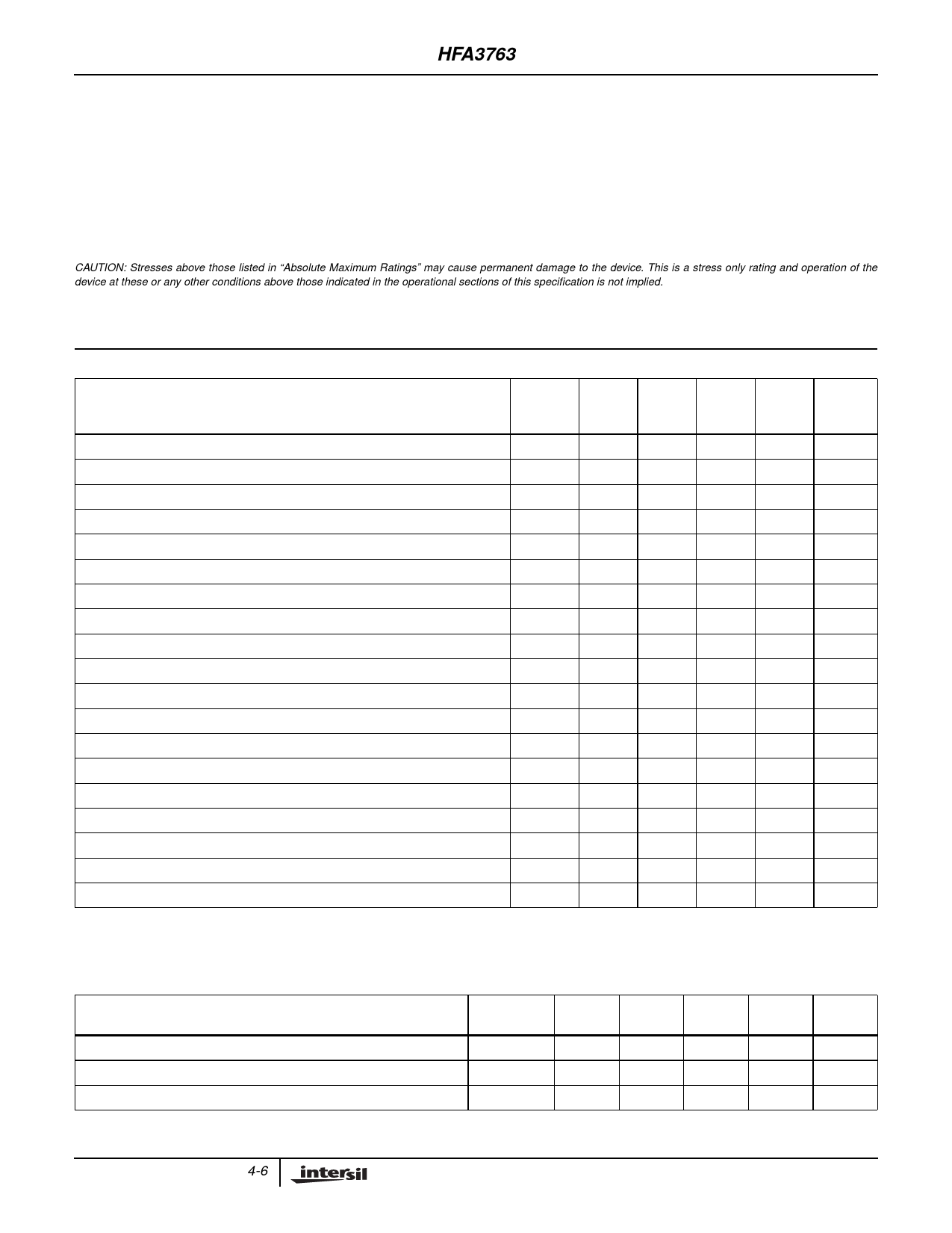
CAUTION: Stresses above those listed in “Absolute Maximum Ratings” may cause permanent damage to the device. This is a stress only rating and operation of the
device at these or any other conditions above those indicated in the operational sections of this specification is not implied.
NOTE:
1. θJA is measured with the component mounted on an evaluation PC board in free air.
Cascaded DC Electrical Specifications VCC = 4.5V to 5.5V, Unless Otherwise Specified
PARAMETER
(NOTE 2)
TEST TEMP
LEVEL
(oC)
MIN
TYP
MAX UNITS
Total Supply Current, TX Mode at 5.5V
A
Full
-
80
106
mA
Shutdown Current at 5.5V
A
Full
-
0.8
1.0
mA
All Digital Inputs VIH (TTL Threshold for All VCC)
A
All Digital Inputs VIL (TTL Threshold for All VCC)
A
High Level Input Current at 5.5V VCC for pin 16 with VIN = 2.4V
A
High Level Input Current at 5.5V VCC for pin 16 with VIN = 4.0V
A
Low Level Input Current at 5.5V VCC for pin 16 with VIN = 0.8V
A
High Level Input Current at 5.5V VCC for pins 17, 20, and 22 with VIN = 2.4V
A
High Level Input Current at 5.5V VCC for pins 17, 20, and 22 with VIN = 4.0V
A
Low Level Input Current at 5.5V VCC for pins 17, 20, and 22 with VIN = 0.8V
A
High Level Input Current at 5.5V VCC for pins 41 and 63 with VIN = 2.4V
A
High Level Input Current at 5.5V VCC for pin 41 with VIN = 4.0V
A
High Level Input Current at 5.5V VCC for pin 63 with VIN = 4.0V
A
Low Level Input Current at 5.5V VCC for pins 41 and 63 with VIN = 0.8V
A
Power Down/Up Switching Speed
C
Full
2.0
-
VCC
V
Full
-0.2
-
0.8
V
Full
-200
-65
0
µA
Full
-150
-30
0
µA
Full
-300
-95
0
µA
Full
0
50
200
µA
Full
0
80
300
µA
Full
0
15
150
µA
Full
-20
1
20
µA
Full
0
110
300
µA
Full
-20
1.5
20
µA
Full
-20
.1
20
µA
25
-
10
-
µs
Reference Voltage
Reference Voltage Variation Over Temperature
A
Full
1.85
2.0
2.15
V
B
Full
-
800
-
µV/oC
Reference Voltage Variation Over Supply Voltage
B
25
-
1.6
-
mV/V
Reference Voltage Minimum Load Resistance
C
25
10
-
-
kΩ
NOTE:
2. A = Production Tested, B = Based on Characterization, C = By Design
Cascaded AC Electrical Specifications, Modulator Performance VCC = 4.5V to 5.5V
PARAMETER
(NOTE 3)
TEMP
TEST LEVEL (oC)
MIN
TYP
MAX
UNITS
IF Modulator Output Power (Note 6)
A
25
-4
1
6
dBm
IF Modulator I/Q Amplitude Balance (Note 4)
B
Full
-1.0
0
+1.0
dB
IF Modulator I/Q Phase Balance (Note 4)
B
Full
-4.0
0
+4.0 Degrees
4-6
Share Link: 