74F786 Ver la hoja de datos (PDF) - Philips Electronics
Número de pieza
componentes Descripción
Lista de partido
74F786 Datasheet PDF : 12 Pages
| |||
Philips Semiconductors
4-bit asynchronous bus arbiter
Product specification
74F786
FUNCTIONAL DESCRIPTION
The BRn inputs have no inherent priority. The arbiter assigns priority
to the incoming requests as they are received, therefore, the first BR
asserted will have the highest priority. When a bus request is
received its corresponding bus grant becomes active, provided that
EN is low. If additional bus requests are made during this time they
are queued. When the first request is removed, the arbiter services
the bus request with the next highest priority. Removing a request
while a previous request is being serviced can cause a grant to be
changed when arbitrating between three or four requests. For that
reason, the user should not remove ungranted requests when
arbitrating between three or four requests. This does not apply to
arbitration between two requests.
If two or more BRn inputs are asserted at precisely the same time,
one of them will be selected at random, and all BGn outputs will be
held in the high state until the selection is made. This guarantees
that an erroneous BGn will not be generated even though a
metastable condition may occur internal to the device. When the EN
is in the high state the BGn outputs are forced high.
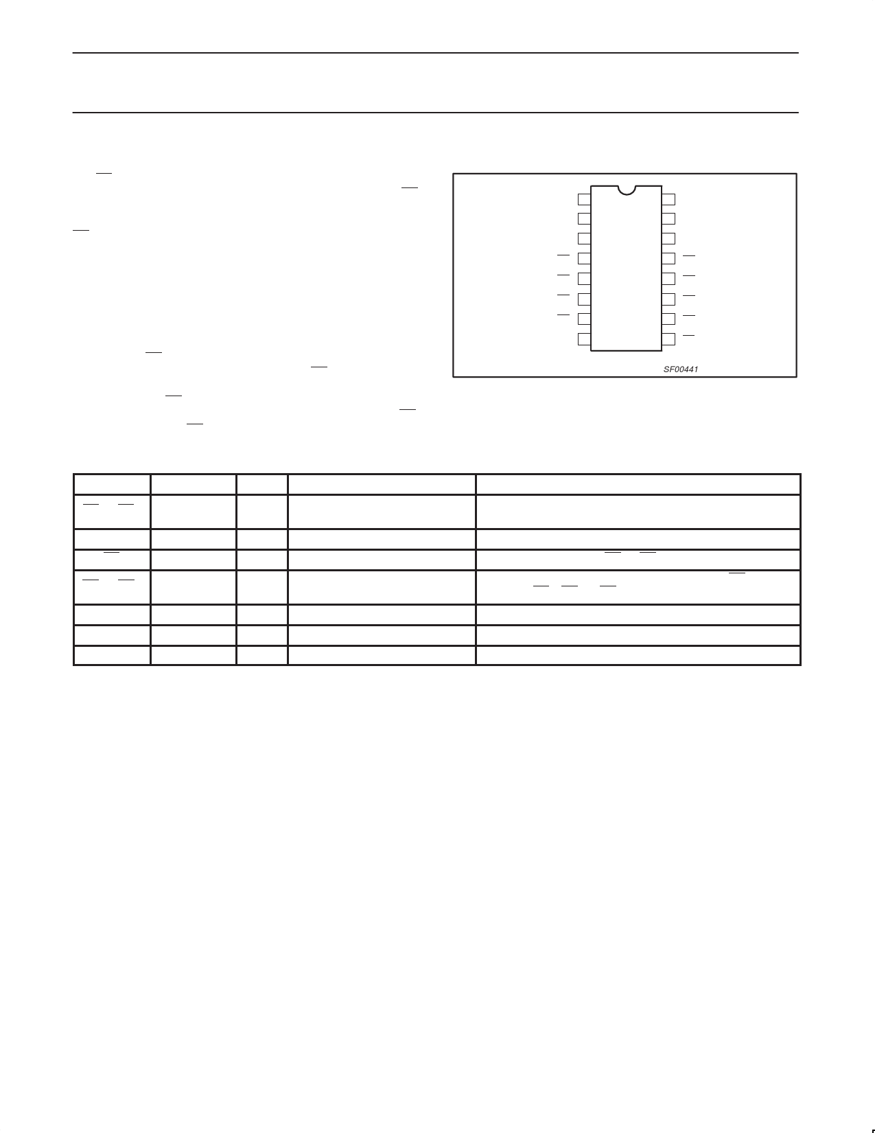
PIN CONFIGURATION
B1
C2
D3
BR0 4
BR1 5
BR2 6
BR3 7
GND 8
16 VCC
15 A
14 YOUT
13 BG0
12 BG1
11 BG2
10 BG3
9 EN
SF00441
PIN DESCRIPTION
SYMBOL
PINS
TYPE
NAME
BR0 – BR3
4, 5, 6, 7
Input Bus request inputs (active low)
A, B, C, D
EN
15, 1, 2, 3
9
Input Inputs of the 4–input AND gate
Input Enable input
BG0 – BG3 13, 12, 11, 10 Output Bus grant outputs (active low)
YOUT
GND
VCC
14
Output Output of the 4–input AND gate
8
Ground ground (0V)
16
Power Positive supply voltages
FUNCTION
The logic of this device arbitrates between these four inputs.
Unused inputs should be tied high.
When low it enables the BG0 – BG3 outputs.
These outputs indicate the selected bus request. BG0 corre-
sponds to BR0, BG1 to BR1, etc.
February 14, 1991
3
Share Link: 