8405202QA Ver la hoja de datos (PDF) - Intersil
Número de pieza
componentes Descripción
Lista de partido
8405202QA Datasheet PDF : 37 Pages
| |||
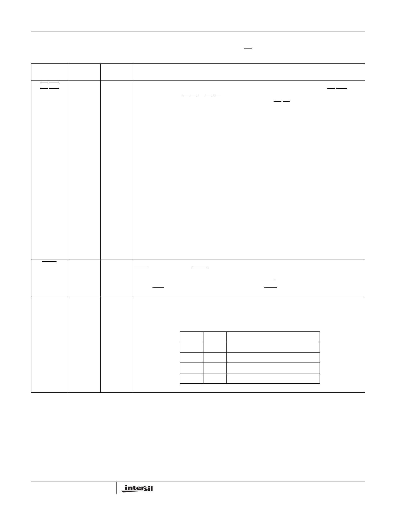
80C86
Maximum Mode System (Continued)
The following pin function descriptions are for the 80C86 system in maximum mode (i.e., MN/MX - GND). Only the pin functions which are unique
to maximum mode are described in the following.
SYMBOL
PIN
NUMBER
TYPE
DESCRIPTION
RQ/GT0
RQ/GT1
31, 30
I/O
REQUEST/GRANT: pins are used by other local bus masters to force the processor to release the
local bus at the end of the processor’s current bus cycle. Each pin is bidirectional with RQ/GTO having
higher priority than RQ/GT1. RQ/GT has an internal pull-up bus hold device so it may be left
unconnected. The request/grant sequence is as follows (see RQ/GT Sequence Timing)
1. A pulse of 1 CLK wide from another local bus master indicates a local bus request (“hold”) to the
80C86 (pulse 1).
2. During a t4 or TI clock cycle, a pulse 1 CLK wide from the 80C86 to the requesting master
(pulse 2) indicates that the 80C86 has allowed the local bus to float and that it will enter the “grant
sequence” state at the next CLK. The CPU’s bus interface unit is disconnected logically from the
local bus during “grant sequence”.
3. A pulse 1 CLK wide from the requesting master indicates to the 80C86 (pulse 3) that the “hold”
request is about to end and that the 80C86 can reclaim the local bus at the next CLK. The CPU
then enters t4 (or TI if no bus cycles pending). Each Master-Master exchange of the local bus is
a sequence of 3 pulses. There must be one idle CLK cycle after each bus exchange. Pulses are
active low.
If the request is made while the CPU is performing a memory cycle, it will release the local bus during
t4 of the cycle when all the following conditions are met:
1. Request occurs on or before t2.
2. Current cycle is not the low byte of a word (on an odd address).
3. Current cycle is not the first acknowledge of an interrupt acknowledge sequence.
4. A locked instruction is not currently executing.
If the local bus is idle when the request is made the two possible events will follow:
1. Local bus will be released during the next cycle.
2. A memory cycle will start within three clocks. Now the four rules for a currently active memory
cycle apply with condition number 1 already satisfied.
LOCK
29
O
LOCK: output indicates that other system bus masters are not to gain control of the system bus while
LOCK is active LOW. The LOCK signal is activated by the “LOCK” prefix instruction and remains active
until the completion of the next instruction. This signal is active LOW, and is held at a high impedance
logic one state during “grant sequence”. In MAX mode, LOCK is automatically generated during t2 of
the first INTA cycle and removed during t2 of the second INTA cycle.
QS1, QSO
24, 25
O
QUEUE STATUS: The queue status is valid during the CLK cycle after which the queue operation is
performed.
QS1 and QS0 provide status to allow external tracking of the internal 80C86 instruction queue. Note
that QS1, QS0 never become high impedance.
QSI QSO
0
0 No Operation
0
1 First byte of op code from queue
1
0 Empty the queue
1
1 Subsequent byte from queue
7
FN2957.3
January 9, 2009
Share Link: 