8405202QA Ver la hoja de datos (PDF) - Intersil
Número de pieza
componentes Descripción
Lista de partido
8405202QA Datasheet PDF : 37 Pages
| |||
80C86
Functional Description
Static Operation
All 80C86 circuitry is of static design. Internal registers,
counters and latches are static and require no refresh as
with dynamic circuit design. This eliminates the minimum
operating frequency restriction placed on other
microprocessors. The CMOS 80C86 can operate from DC to
the specified upper frequency limit. The processor clock may
be stopped in either state (HIGH/LOW) and held there
indefinitely. This type of operation is especially useful for
system debug or power critical applications.
The 80C86 can be single stepped using only the CPU clock.
This state can be maintained as long as is necessary. Single
step clock operation allows simple interface circuitry to
provide critical information for bringing up your system.
Static design also allows very low frequency operation (down
to DC). In a power critical situation, this can provide
extremely low power operation since 80C86 power
dissipation is directly related to operating frequency. As the
system frequency is reduced, so is the operating power until,
ultimately, at a DC input frequency, the 80C86 power
requirement is the standby current, (500µA maximum).
Internal Architecture
The internal functions of the 80C86 processor are partitioned
logically into two processing units. The first is the Bus
Interface Unit (BlU) and the second is the Execution Unit
(EU) as shown in the “Functional Diagram” on page 3.
These units can interact directly, but for the most part perform
as separate asynchronous operational processors. The bus
interface unit provides the functions related to instruction
fetching and queuing, operand fetch and store, and address
relocation. This unit also provides the basic bus control. The
overlap of instruction pre-fetching provided by this unit serves
to increase processor performance through improved bus
bandwidth utilization. Up to 6 bytes of the instruction stream
can be queued while waiting for decoding and execution.
The instruction stream queuing mechanism allows the BIU to
keep the memory utilized very efficiently. Whenever there is
space for at least 2 bytes in the queue, the BlU will attempt a
word fetch memory cycle. This greatly reduces “dead-time”
on the memory bus. The queue acts as a First-In-First-Out
(FIFO) buffer, from which the EU extracts instruction bytes
as required. If the queue is empty (following a branch
instruction, for example), the first byte into the queue
immediately becomes available to the EU.
The execution unit receives pre-fetched instructions from the
BlU queue and provides un-relocated operand addresses to
the BlU. Memory operands are passed through the BIU for
processing by the EU, which passes results to the BIU for
storage.
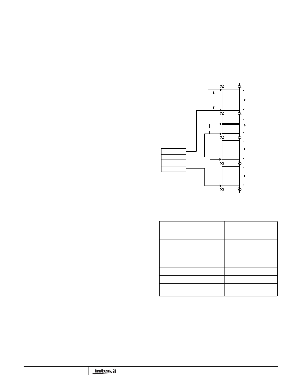
Memory Organization
The processor provides a 20-bit address to memory, which
locates the byte being referenced. The memory is organized
as a linear array of up to 1 million bytes, addressed as
00000(H) to FFFFF(H). The memory is logically divided into
code, data, extra and stack segments of up to 64k bytes
each, with each segment falling on 16-byte boundaries
(see Figure 1).
FFFFFH
64k-BIT
SEGMENT
REGISTER FILE
CS
SS
DS
ES
+ OFFSET
CODE SEGMENT
XXXXOH
STACK SEGMENT
DATA SEGMENT
EXTRA SEGMENT
00000H
FIGURE 1. 80C86 MEMORY ORGANIZATION
TYPE OF
MEMORY
REFERENCE
Instruction Fetch
Stack Operation
Variable (except
following)
String Source
String Destination
BP Used As Base
Register
TABLE 1.
DEFAULT
SEGMENT
BASE
ALTERNATE
SEGMENT
BASE
OFFSET
CS
None
IP
SS
None
SP
DS
CS, ES, SS Effective
Address
DS
CS, ES, SS SI
ES
None
DI
SS
CS, DS, ES Effective
Address
All memory references are made relative to base addresses
contained in high speed segment registers. The segment
types were chosen based on the addressing needs of
programs. The segment register to be selected is
automatically chosen according to the specific rules of
Table 1. All information in one segment type share the same
logical attributes (e.g. code or data). By structuring memory
into re-locatable areas of similar characteristics and by
automatically selecting segment registers, programs are
shorter, faster and more structured (see Table 1).
8
FN2957.3
January 9, 2009
Share Link: 