IDT821068 Ver la hoja de datos (PDF) - Integrated Device Technology
Número de pieza
componentes Descripción
Lista de partido
IDT821068 Datasheet PDF : 45 Pages
| |||
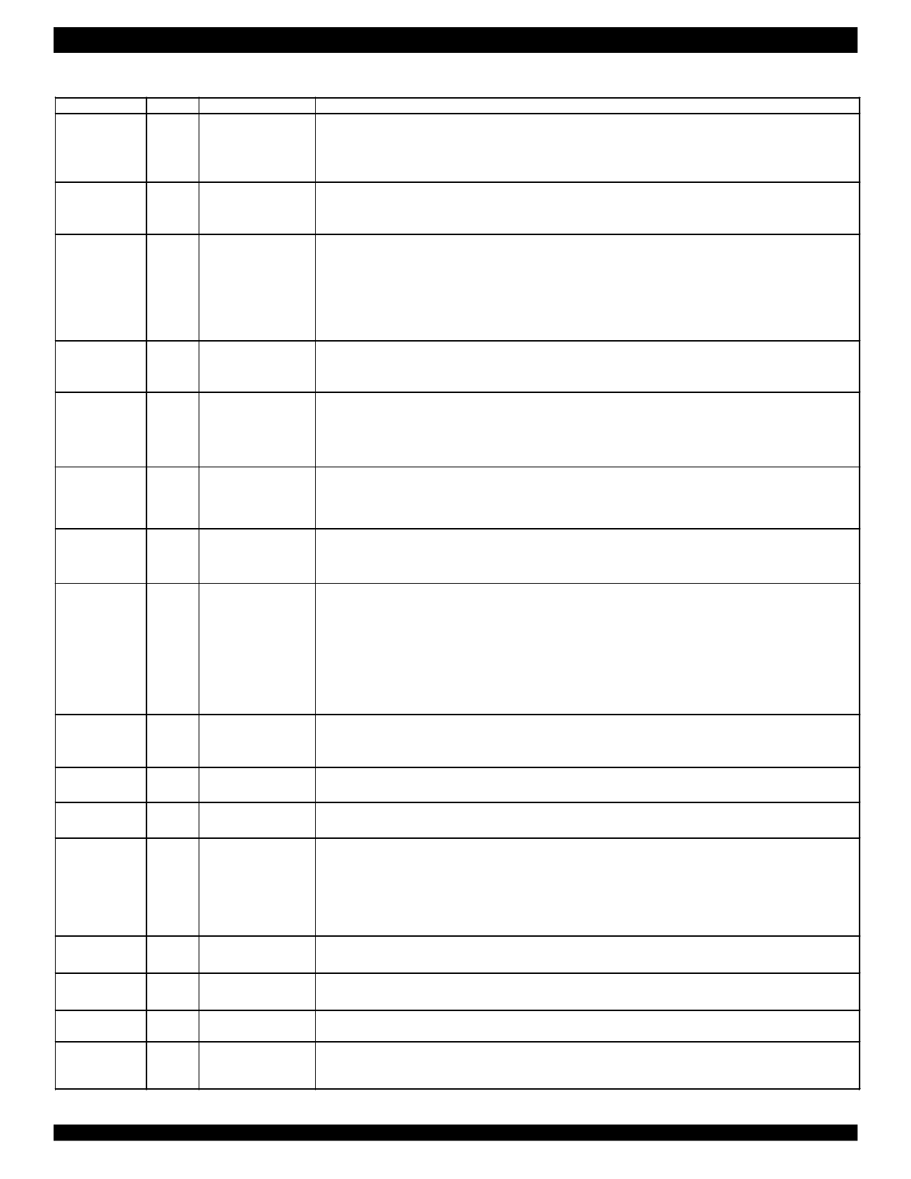
IDT821068 OCTAL PROGRAMMABLE PCM CODEC
INDUSTRIAL TEMPERATURE RANGE
PIN DESCRIPTION (CONTINUED)
Name
DR2
FS/FSC
Type
I
I
Pin Number
48
52
Description
Receive PCM Data Input (For MPI).
PCM data is shifted into DR1 or DR2 following the BCLK. PCM data can input from DR1 and DR2 as
selected by serial port.
This pin is not used in GCI mode
Frame Synchronization signal (For MPI)/Frame Sync signal (For GCI).
In MPI mode, FS is an 8 kHz synchronization clock that identifies the beginning of the PCM frame.
In GCI mode, FSC is an 8 kHz signal that identifies the beginning of Timeslot 0 in the GCI frame.
BCLK/DCL
I
Bit Clock (For MPI)/Data Clock (For GCI).
In MPI mode, BCLK pin clocks out the PCM data on DX1 or DX2 pin and clock in PCM data from DR1 or
53
DR2 pin. It may vary from 512kHz to 8.192 MHz, and is required to be synchronous with FS.
In GCI mode, DCL pin is either 2.048 MHz or 4.096 MHz. The frequency is selected by CI/DOUBLE pin.
When CI/DOUBLE pin is low, DCL will be 2.048 MHz; when CI/DOUBLE pin is high, DCL will be 4.096 MHz.
It is recommended to connect MCLK and DCL pin together.
TSX1
TSX2
O
47
50
Timeslot Indicator Output (For MPI).
This pin pulses low during the receive timeslot. A low on this pin indicates DX1/DX2 output.
These two open-drain pins are not used in GCI mode.
CS
I
CI/DOUBLE
I
CO
O
Chip Selection.
109
In MPI mode, a low level on this pin enables the Serial Control Interface.
In GCI mode, a low level on this pin configures a Compressed GCI operation, while a high level on this pin
configures a Linear GCI operation.
Serial Control Interface Data Input (For MPI)/Double DCL (For GCI).
111
In MPI mode, data input on this pin can control both CODEC and SLIC.
In GCI mode, this pin is used to determine the frequency of DCL. When low, DCL will be 2.048 MHz; when
high, DCL will be 4.096 MHz.
Serial Control Interface Data Output (For MPI).
112
This pin is used to monitor SLIC working status. It is in high impedance state when CS is high.
This pin is not used in GCI mode.
CCLK/TS
I
Serial Control Interface Clock (For MPI)/Timeslot Selection (For GCI).
In MPI mode, this is the clock for Serial Control Interface. It can be up to 8.192 MHz.
In Compressed GCI mode, this pin indicates which half of 8 continuous GCI timeslots is used. When this pin
110
is low, timeslots 0-3 are selected; when this pin is high, timeslots 4-7 are selected.
In Linear GCI mode, this pin indicates which half of 8 continuous GCI timeslots is used for voice signal.
When this pin is low, timeslots 0-3 are used as Monitor channel and C/I octet, timeslots 4-7 are used for
linear voice; when this pin is high, timeslots 4-7 are used for linear voice, timeslots 0-3 are used as Monitor
channel and C/I octet.
MPI
RESET
INT
MCLK
CHCLK1
CHCLK2
CNF1
CNF2
NC
MPI/GCI Select.
I
108
This pin is used to determine which operation mode the IDT821068 works in. When this pin is low, MPI/PCM
mode is selected; When this pin is high, GCI mode is selected.
I
122
Reset Input.
Forces the device to default mode. Active low.
O
113
Interrupt Output Pin.
Active low interrupt signal for ch1-ch8, open-drain. It reflects the changes on SLIC pins.
Master Clock.
Master clock provides the clock for DSP.
I
54
In MPI mode, it can be 1.536 MHz, 1.544 MHz, 2.048 MHz, 3.072 MHz, 3.088 MHZ, 4.096 MHz, 6.144 MHz,
6.176 MHz or 8.192 MHz. It can be asynchronous to BCLK.
In GCI mode, it is recommended to connect MCLK and DCL pin together. The frequency of MCLK can be
2.048 MHz or 4.096 MHz. See BCLK/DCL pin description.
O
57
Chopper Clock Output.
Provides a programmable (2 -28 ms) output signal synchronous to MCLK.
O
56
Chopper Clock Output.
Provides a programmable 256 kHz, or 512 kHz or 16.384 MHz output signal synchronous to MCLK.
-
13
90
Capacitor Noise Filter.
44, 51, 58, 114
-
115,116,117,118 No Connection.
119,120,121,123
4
Share Link: 