IDT821068 Ver la hoja de datos (PDF) - Integrated Device Technology
Número de pieza
componentes Descripción
Lista de partido
IDT821068 Datasheet PDF : 45 Pages
| |||
IDT821068 OCTAL PROGRAMMABLE PCM CODEC
INDUSTRIAL TEMPERATURE RANGE
GCI MODE
In GCI mode, the GCI interface provides communication of both
control and voice data between the GCI bus and SLIC over a pair of
pins (DD and DU). The IDT821068 follows the GCI standard where
voice and control data for eight channels are combined into one serial
bit stream: Data Upstream is sent out of the DU pin and Data
Downstream is received on the DD pin. The data transmission is
controlled by the Data Clock (DCL) and Frame Synchronization (FSC)
signals. The Frame Sync (FSC) pulse identifies the beginning of the
Transmit and Receive frames and all GCI time slots refer to it. The
DCL signal can be 2.048MHz or 4.096 MHz, decided by DOUBLE
pin. The IDT821068 adjusts internal timing to accommodate signal
(2.048 MHz) or double (4.096 MHz) clock rate. A complete GCI frame
is sent upstream on DU pin and received downstream on DD pin
every 125 µs.
In GCI mode, IDT821068 supports compressed and linear voice
data format. To make the selection, users should set the MPI and CS
pin to correct level as shown in the following table, and at the same
time, set the DMS bit in Global Command accordingly.
MPI CS
1
0
1
1
Voice Data Format
Compressed GCI
Linear GCI
Compressed GCI Structure
In GCI compressed mode, the Data Upstream Interface logic con-
trols the transmission of data onto the GCI bus. One GCI frame con-
sists of 8 GCI time slots, and one GCI time slot consists of four 8-bit
bytes as described below:
- Two voice data bytes from the A-law or µ-law compressor for two
different channels. For easy description, we name the two channels as
channel A and channel B. The compressed voice data bytes for chan-
nel A and B are 8-bit wide;
- One monitor channel byte, which is used for reading control data
from the device for channel A and B;
- One C/I channel byte, which contains a 6 bit width C/I channel sub-
byte together with an MX bit and an MR bit. All real time signaling in-
formation is carried on the C/I channel sub-byte. The MX (Monitor
Transmit) bit and MR (Monitor Receive) bits are used for handshaking
functions for channel A and B. Both MX and MR are active low.
The data structure of the Data Downstream is as same as that of
Upstream. The Data Downstream Interface logic controls the reception
of data bytes from the GCI bus. The two compressed voice channel
data bytes of the GCI time slot are transferred to the A-law or µ-law ex-
pansion logic circuit. The expanded data is passed to the receive path
of the signal processor. The monitor channel and C/I channel bytes are
transferred to the GCI control logic for processing.
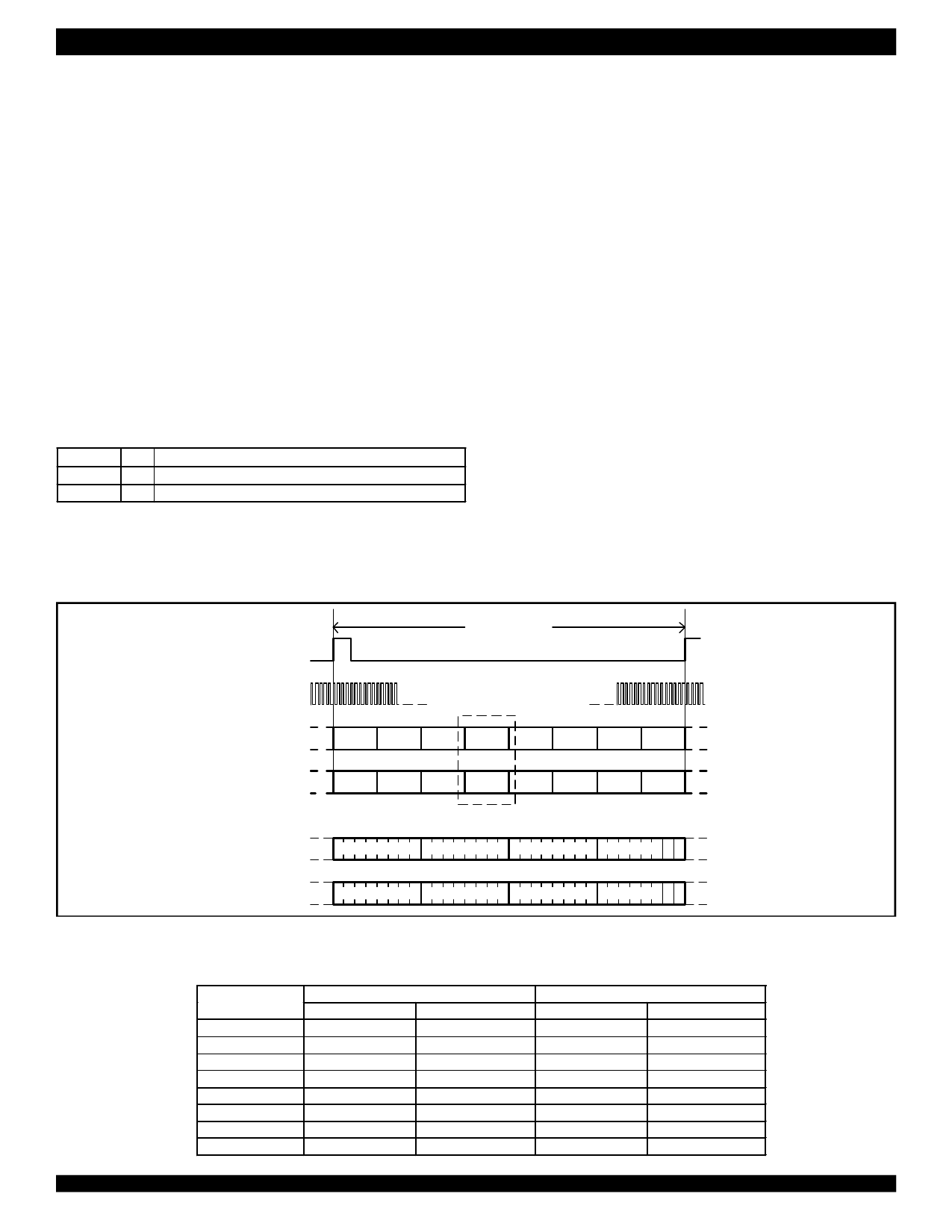
Figure 4 shows the overall compressed GCI frame structure.
In compressed operation, four time slots are required to access the
eight channels of IDT821068. The GCI time slot assignment is
determined by the TS pin as shown in Table 1.
125 µs
FSC
DCL
DD
TS0 TS1 TS2 TS3 TS4 TS5 TS6 TS7
Detail
DU
TS0 TS1 TS2 TS3 TS4 TS5 TS6 TS7
Detail
DD
Voice Channel A
Voice Channel B
Monitor Channel C/I Channel
MM
RX
DU
Voice Channel A
Voice Channel B
Monitor Channel C/I Channel
MM
RX
Figure 4. Compressed GCI Frame Structure
Table 1 - Time Slot Selection for compressed GCI
IDT821068
Channels
1
2
3
4
5
6
7
8
Timeslot
Timeslot0
Timeslot0
Timeslot1
Timeslot1
Timeslot2
Timeslot2
Timeslot3
Timeslot3
TS = 0
Voice Channel
A
B
A
B
A
B
A
B
Timeslot
Timeslot4
Timeslot4
Timeslot5
Timeslot5
Timeslot6
Timeslot6
Timeslot7
Timeslot7
TS = 1
Voice Channel
A
B
A
B
A
B
A
B
7
Share Link: 