MIC1832 Ver la hoja de datos (PDF) - Micrel
Número de pieza
componentes Descripción
Lista de partido
MIC1832 Datasheet PDF : 7 Pages
| |||
MIC1832
Applications Information
Power Monitor
The /RST and RST pins are asserted whenever VCC falls
below the reset threshold voltage as determined by the TOL
pin. A 5% tolerance level (4.62V reset threshold voltage) can
be selected by connecting the TOL pin to ground and a 10%
tolerance can be selected by connecting the TOL pin to VCC.
The reset pins will remain asserted for a period of 250ms
after VCC has risen above the reset threshold voltage. The
reset function ensures the microprocessor is properly reset
and powers up into a known condition after a power failure.
/RST will remain valid with VCC as low as 1.4V.
Watchdog Timer
The microprocessor can be mounted by connecting the /ST
pin (watchdog input) to a bus line or I/O line. If a high-to-low
does not occur on the/ST pin within the watchdog timeout
Micrel, Inc.
period (determined by the TD pin, see Table 1.), the /RST and
the RST will remain asserted for 250ms when this occurs. A
minimum pulse of 75ns or any transition high-to-low on the
/ST pin will reset the watchdog timer. The watchdog timer
will be reset if /ST sees a valid transition within the watchdog
timeout period.
Pushbutton Reset Input
The /PBRST input can be driven with a manual pushbutton
switch or with external logic signals. the input is internally
debounced and requires an active low signal to force the
reset outputs into their active states. The /PBRST input will
recognize any pulse that is 20ms in duration or greater and
will ignore all pulses that are less than 1ms in duration.
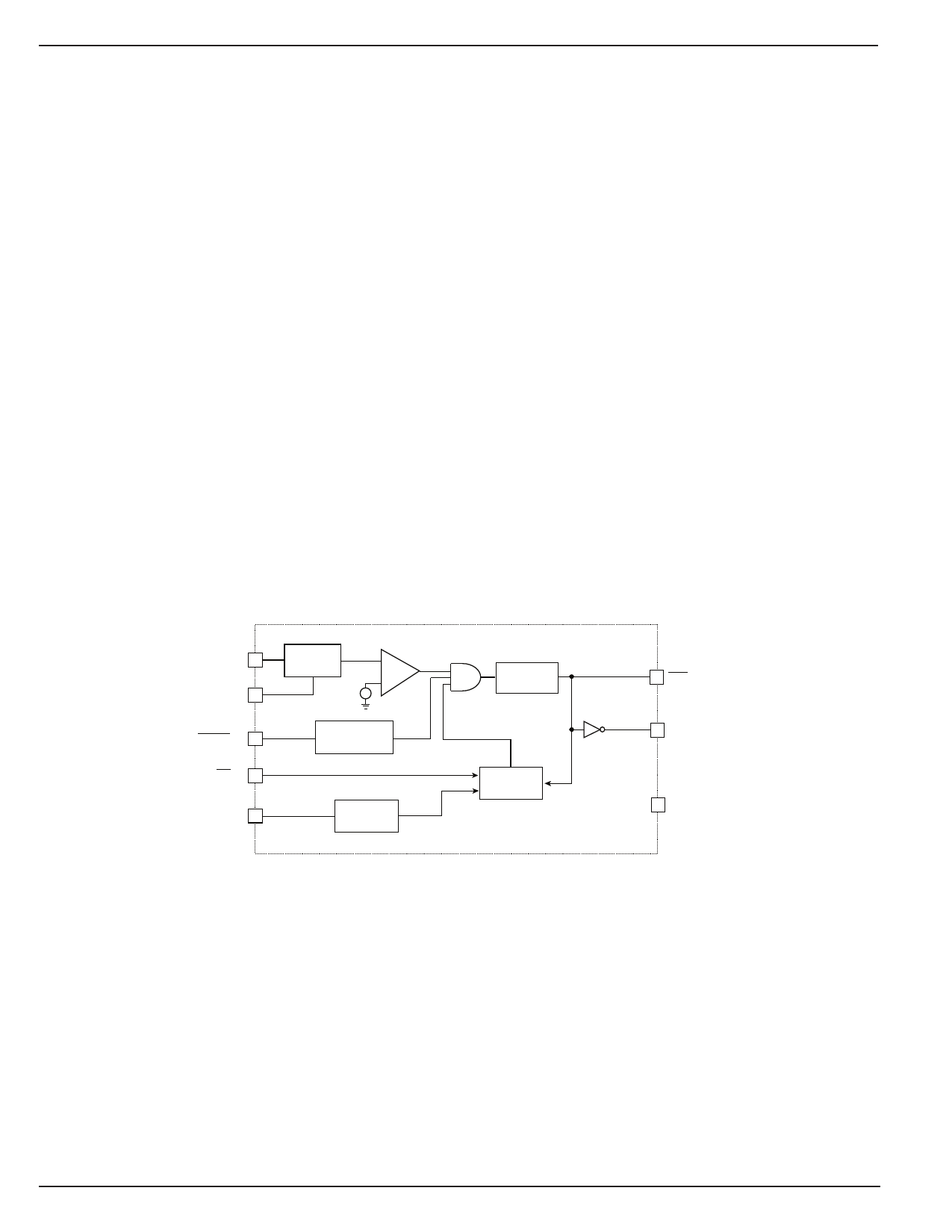
Block Diagram
VCC (8)
TOL (3)
PBRST (1)
ST (7)
TD (2)
TRIP POINT
SELECT
+
-
REF
MANUAL RESET
DEBOUNCE
TIMEOUT
SELECT
RESET
GENERATOR
WATCHDOG
TIMER
RST (6)
RST (5)
GND (4)
MIC1832
6
January 2006
Share Link: 