PCD5032H Ver la hoja de datos (PDF) - Philips Electronics
Número de pieza
componentes Descripción
Lista de partido
PCD5032H Datasheet PDF : 24 Pages
| |||
Philips Semiconductors
ADPCM CODEC for digital cordless
telephones
Product specification
PCD5032
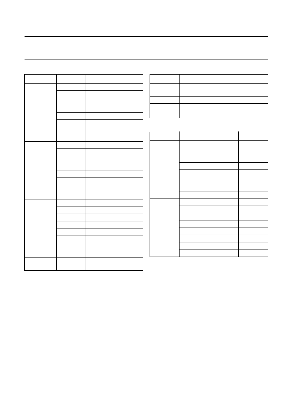
Table 2 Overview of gain control options
FUNCTION I2C-CODE
Receiver
01XXX101
gain (relative) 01XXX110
01XXX111
01XXX000
01XXX001
01XXX010
01XXX011
01XXX100
Receiver
volume
01000XXX
01001XXX
01010XXX
01011XXX
01100XXX
01101XXX
01110XXX
01111XXX
Transmitter 10XXX101
gain (relative) 10XXX110
10XXX111
10XXX000
10XXX001
10XXX010
10XXX011
10XXX100
Transmitter 10XX1XXX
mute
GAIN
−3 dB
−2 dB
−1 dB
0 dB
+1 dB
+2 dB
+3 dB
+4 dB
0 dB
−6 dB
−12 dB
−18 dB
−24 dB
−30 dB
−36 dB
RX MUTE
−3 dB
−2 dB
−1 dB
0 dB
+1 dB
+2 dB
+3 dB
+4 dB
TX MUTE
NOTE
default
default
default
default OFF
7.2.2 SIDETONE
With the I2C-bus interface the (local) sidetone level can be
set to −12, −18, −24 dB, or switched off. See Table 3.
The sidetone level is independent of the receiver volume
control setting.
7.2.3 TONE GENERATOR AND RINGER
The PCD5032 contains a programmable tone generator
which can be used for generating ringer tones (BZ+, BZ−)
or local information tones in the receive path (RE+, RE−).
By setting the TONE bit (bit 3) in the operation mode
register, the tone output will be directed to the receiver
DAC, otherwise the tones will be sent to the ringer output
stage. Table 4 shows the possible frequency and volume
settings.
Table 3 Sidetone level options
FUNCTION I2C-CODE
OPTION
NOTE
Sidetone
1000XXXX
1001XXXX
1010XXXX
1011XXXX
No local
sidetone
default
Level = −12 dB
Level = −18 dB
Level = −24 dB
Table 4 Tone output frequency/volume options
FUNCTION I2C-CODE OPTION
NOTE
Volume
(relative)
Frequency
11XXX000
11XXX001
11XXX010
11XXX011
11XXX100
11XXX101
11XXX110
11XXX111
11000XXX
11001XXX
11010XXX
11011XXX
11100XXX
11101XXX
11110XXX
11111XXX
Signal off
−29 dB
−23 dB
−17 dB
−11 dB
−5 dB
−0 dB
+4 dB
400 Hz
421 Hz
444 Hz
800 Hz
1000 Hz
1067 Hz
1333 Hz
2000 Hz
default
sinewave
sinewave
sinewave
sinewave
sinewave
sinewave
squarewave
The ringer output (BZ) is differential and is intended for
low-ohmic devices. If the ringer is switched off then both
outputs are low. The output signal is a pulse density
modulated block wave (on a 32 kHz basic pulse rate) to
generate a sinewave-like output signal, see Fig.9. Volume
is controlled by changing the pulse width of each pulse.
In the square wave mode a full square wave is generated
and results in the maximum volume. The volume settings
(in dB) are given for the first harmonic signal component.
1997 Apr 03
11
Share Link: 