PCD5043 Ver la hoja de datos (PDF) - Philips Electronics
Número de pieza
componentes Descripción
Lista de partido
PCD5043 Datasheet PDF : 24 Pages
| |||
Philips Semiconductors
DECT burst mode controller
Objective specification
PCD5043
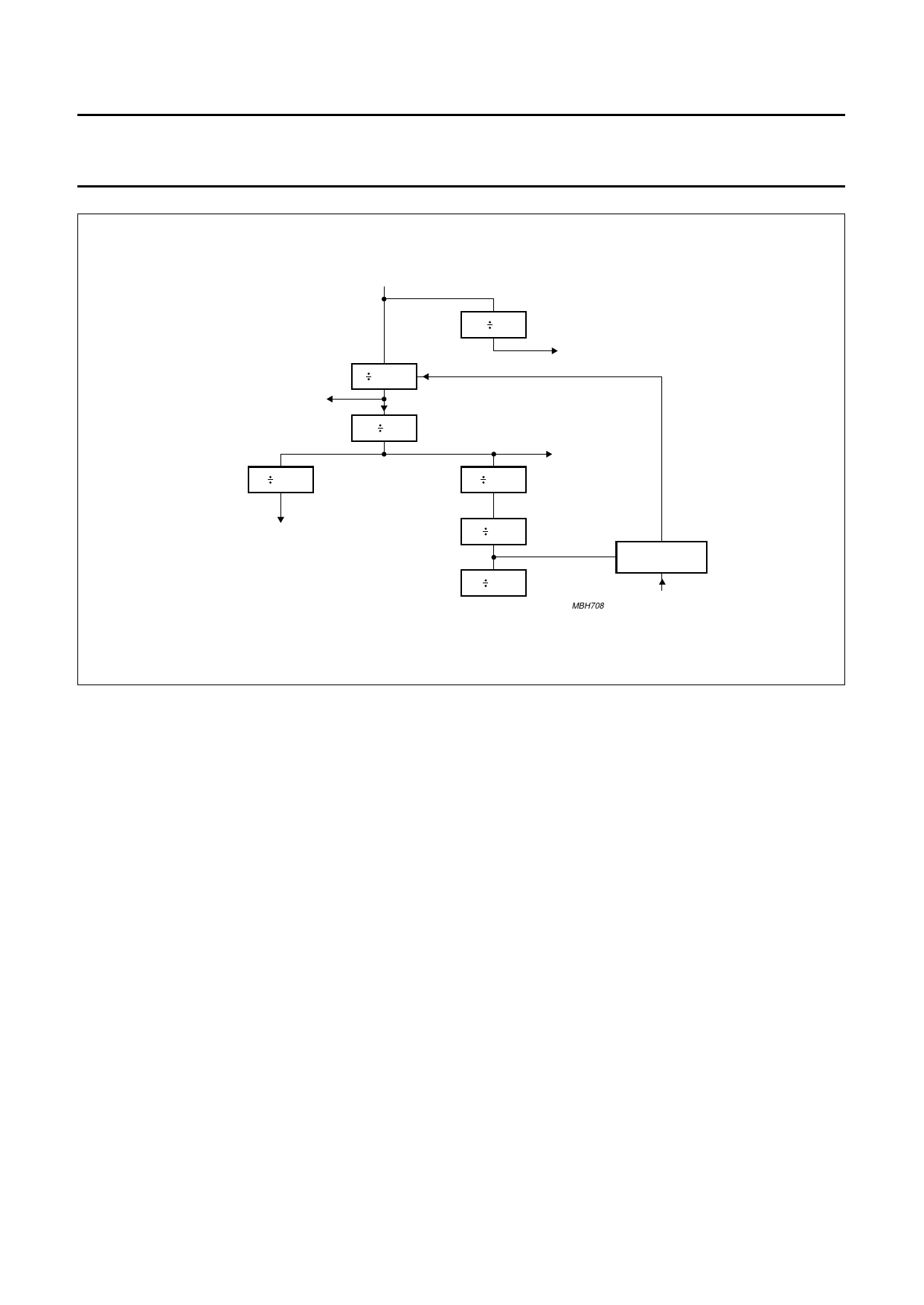
handbook, full pagewidth
13.824 MHz system clock
3.456 MHz system
clock for ADPCM codec
144
4 (±1)
2
6.912 MHz system clock
clock corrections in this level
unless disabled PCD5041's mode register
3
bit counter
480
1152 kHz
system/bit clock
FSx signals
(8 kHz)
slot counter
24
slot counter
16
100 Hz
frame sync
COMPARATOR
MBH708
'SYNC' event
Fig.3 Internal clocking scheme of the PCD5043.
6.4 Speech interface
The speech interface block performs the following
functions:
• Connection to a 1152 kbits/s interface in a handset and
a simple base station in the so called ‘12 slot mode’
• Connection to a n x 64 kbits/s interface in base stations
in the so called ‘32 slot mode’
• Autonomous storing/fetching of ADPCM speech data
in/from the PCD5043’s common data memory, using
internal addressing logic
• Muting of speech data
• Local call.
6.4.1 12-SLOT MODE
The 12-slot mode is selected if up to 4 ADPCM codecs are
connected to the PCD5043, where the PCD5043 is the
master of these codecs. In a handset, or in a simple base
stations which is connected with up to 4 analog lines to the
public network, the PCD5043 is master of the codecs.
Each codec is connected with a separate framing
reference signal (FS1 to FS4) to the PCD5043. In the
QFP64 package, 2 framing signals FS1 and FS2 are
available, whereas in the LQFP80 package 4 framing
signals can be used (FS1 to FS4). When more codecs are
to be connected, the FS5 to FS12 signals have to be
generated externally. When using the framing signals
FS1 to FS4, no interface logic is required when using the
PCD5032 ADPCM codec.
A speech-slot control table is used to determine where to
store/fetch speech data for transmission and reception.
The hardware speech-interface is capable of addressing
the right speech buffer for the relevant speech slot, and will
maintain a counter carrying the offset to the correct
stored/fetched address.
6.4.2 32-SLOT MODE
The 32-slot mode is used to connect the PCD5043 to a
digital interface with a data rate of n × 64 kbits/s; where
n = 1 to 32 is the number of speech slots. This equates to
data rates from 64 kbits/s to 2048 kbits/s.
Up to 12 of the 32 speech slots can be used
simultaneously. The same kind of speech-slot control table
used in the 12-slot mode is used for the 32-slot mode.
6.4.3 MUTING
Due to various reasons the quality of the incoming speech
data may be degraded significantly. By muting the speech
1996 Oct 31
9
Share Link: 