PE42672 Ver la hoja de datos (PDF) - Peregrine Semiconductor Corp.
Número de pieza
componentes Descripción
Lista de partido
PE42672 Datasheet PDF : 4 Pages
| |||
PE42672
Advance Information
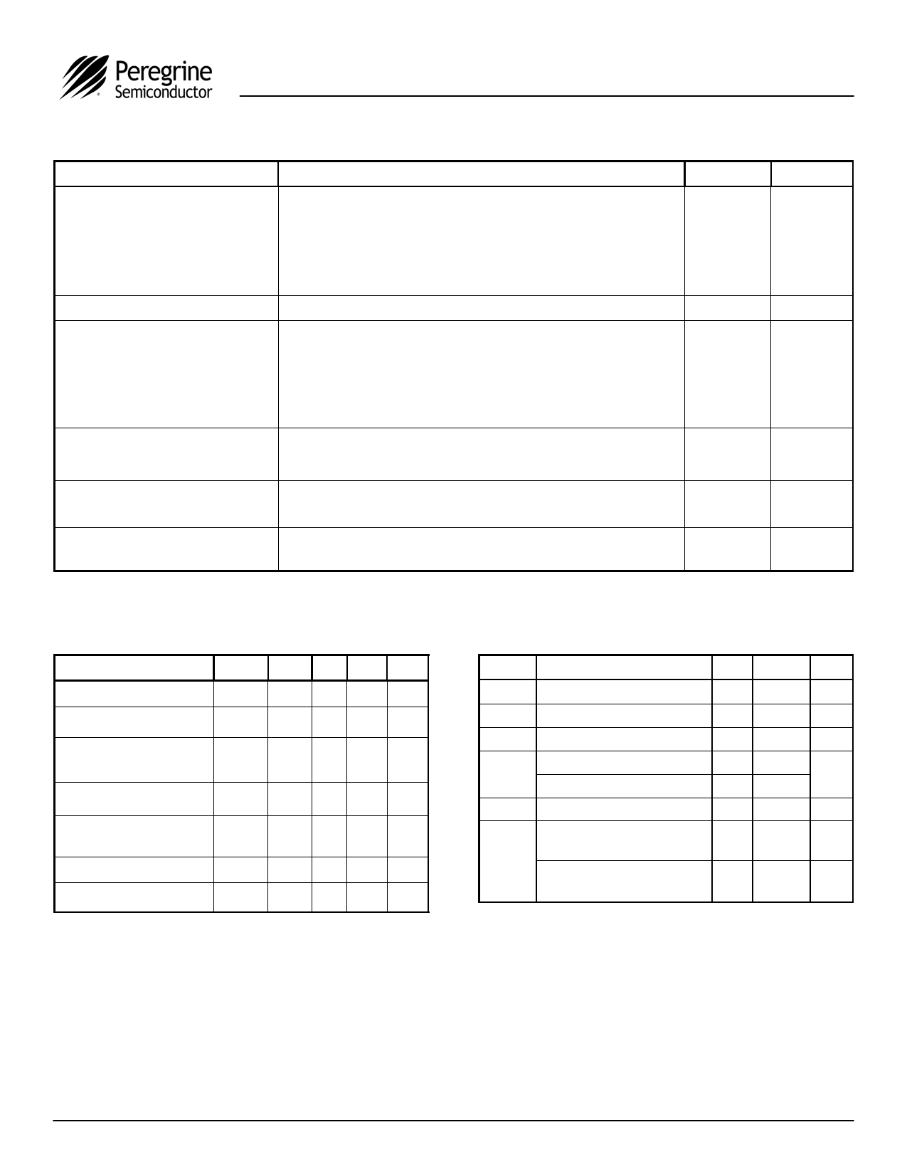
Table 1. Target Electrical Specifications @ 25 °C, VDD = 2.75 V
Parameter
Condition
Insertion loss1
TX - Ant (850 / 900)
TX - Ant (1800 / 1900)
TX - Ant ( 2200 UMTS )
RX - Ant (850 / 900)
RX - Ant (1800 / 1900)
Return Loss
Port under test in on state
Isolation
TX - RX (850 / 900)
TX - RX (1800 / 1900)
TX - TX (850 / 900)
TX - TX (1800 / 1900)
TX1 - RX (1900 / 2200)
2nd Harmonic
TX 850 / 900 MHz, +35 dBm output power, 50 Ω
TX 1800 / 1900 MHz, +33 dBm output power, 50 Ω
3rd Harmonic
TX 850 / 900 MHz, +35 dBm output power, 50 Ω
TX 1800 / 1900 MHz, +33 dBm output power, 50 Ω
IMD3 distortion at 2.14 GHz
TX1 Measured at 2.14 GHz at Ant port, input +20 dBm CW signal
at 1.95 GHz and -15 dBm CW signal at 1.76 GHz
Note: 1. Insertion loss specified with optimal impedance matching.
Typ
0.5
0.7
0.8
0.8
1.0
20
44
38
29
23
37
-84
-80
-77
-73
-111
Units
dB
dB
dB
dB
dB
dB
dB
dB
dB
dB
dB
dBc
dBc
dBc
dBc
dBm
Table 2. Operating Ranges
Parameter
Symbol Min Typ Max Units
Temperature range
TOP
-40
+85 °C
VDD Supply Voltage
VDD
2.65 2.75 2.85 V
IDD Power Supply Current
(VDD = 2.75 V)
TX input power2
(VSWR ≤ 3:1)
RX input power2
(VSWR =1:1)
Control Voltage High
Control Voltage Low
IDD
13 50 µA
PIN
+35 dBm
PIN
VIH
1.4
VIL
+20 dBm
V
0.4 V
Note: 2. Assumes RF input period of 4620 µs and duty cycle of 50%.
Table 3. Absolute Maximum Ratings
Symbol
Parameter/Conditions
Min Max Units
VDD Power supply voltage
-0.3
VI Voltage on any input
-0.3
TST Storage temperature range
-65
TX input power (50 Ω) 3,4
PIN(50 Ω)
RX input power (50 Ω) 3,4
PIN (∞:1) TX input power (VSWR = ∞:1) 3,4
ESD Voltage (HBM, MIL_STD
883 Method 3015.7)
VESD
ESD Voltage at ANT Port
(IEC 61000-4-2)
4.0
VDD+ 0.3
+150
+38
+23
+35
1500
1700
V
V
°C
dBm
dBm
V
V
Note: 3. Assumes RF input period of 4620 µs and duty cycle of 50%.
4. VDD within operating range specified in Table 2.
Part performance is not guaranteed under these
conditions. Exposure to absolute maximum
conditions for extended periods of time may
adversely affect reliability. Stresses in excess of
absolute maximum ratings may cause permanent
damage.
©2005 Peregrine Semiconductor Corp. All rights reserved.
Page 2 of 4
Document No. 70-0197-01 │ UltraCMOS™ RFIC Solutions
Contact sales@psemi.com for full version of datasheet
Share Link: 