RTL8019AS Ver la hoja de datos (PDF) - Realtek Semiconductor
Número de pieza
componentes Descripción
Lista de partido
RTL8019AS
Realtek Semiconductor

RTL8019AS Datasheet PDF : 50 Pages
| |||
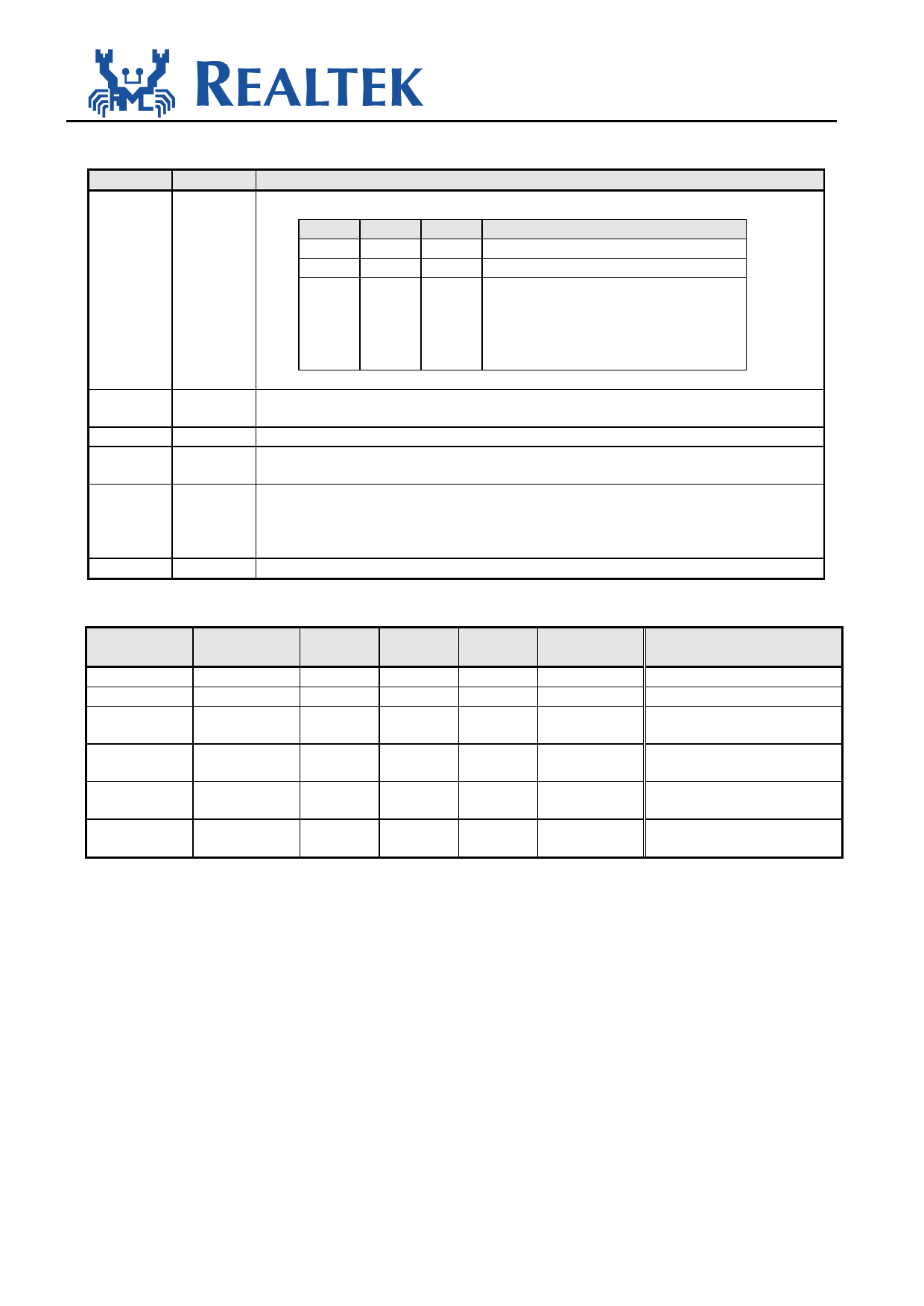
SPECIFICATION
RTL8019AS
CONFIG0: RTL8019AS Configuration Register 0 (03H; Type=R except Bit[7:6]=R/W)
Bit
Symbol
Description
7-6
VERID Version ID: These two bits are defined as below.
Bit7 Bit6 Type
Mode
1
1
R RTL8019
0
0
R RTL8019A
0
0
R/W RTL8019AS, these two bits are all "0"
when power on, but can be written in
RTL8019AS's config write enable mode
(EEM0=EEM1=1). Software uses these
differences to identify the chip.
5
AUI This bit is set when external MAU is used on AUI interface. Therefore it is set when in
10Base5 mode or the AUI input pin is high.
4
PNPJP This bit is set when PNP jumper pin is pulled high externally.
3
JP
This bit reflects the state of JP input. It, when set, indicates the RTL8019 is in jumper
mode.
2
BNC When set, this bit indicates that the RTL8019 is using the 10Base2 thin cable as its
networking medium. This bit will be set in the following 2 cases:
(1) PL1=PL0=0 (auto-detect) and link test fails
(2) PL1=PL0=1 (10 Base 2)
1-0
0
Always 0s.
The following table describes the behavior of bits and pins for cabling media.
Media Type
10Base5
10Base2
10BaseT
Link disabled
Auto detect
Link OK
Auto detect
Link fail
Auto detect
Link fail
AUI Input
x
x
x
x
L
H
Selected
Media
AUI
BNC
UTP
AUI Bit
1
0
0
BNC Bit
0
1
0
UTP
0
0
BNC
0
1
AUI
1
0
LEDBNC
Output
L
H
L
L
H
L
Original BNC bit in 8019
(For reference only)
0
1
0
0
1
1
8019AS.doc
18
2001-04-02
Share Link: