RTL8019AS Ver la hoja de datos (PDF) - Realtek Semiconductor
Número de pieza
componentes Descripción
Lista de partido
RTL8019AS
Realtek Semiconductor

RTL8019AS Datasheet PDF : 50 Pages
| |||
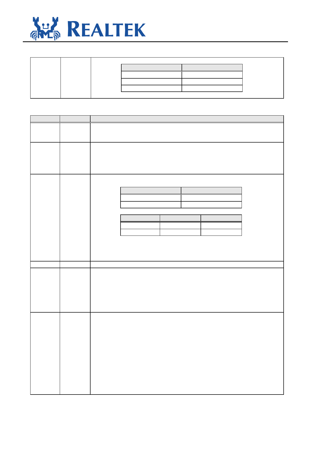
SPECIFICATION
RTL8019AS
BROM size
16K
32K
64K
BA14
high
SA14
SA14
BA15
high
high
SA15
CONFIG3: RTL8019AS Configuration Register 3 (06H; Type=R except Bit[2:1]=R/W)
Bit
Symbol
Description
7
PNP
This bit is negligible in jumper mode. In jumperless mode it, when set, indicates the
RTL8019AS is operating in Plug and Play mode. This bit is set when the PNP pin is
high or the PNP bit in 9346 is set in jumperless mode.
6
FUDUP When this bit is set, RTL8019AS is set to the full-duplex mode which enables
simultaneously transmission and reception on the twisted-pair link to a full-duplex
Ethernet switching hub. This feature not only increases the channel bandwidth from 10
to 20 Mbps but also avoids the performance degrading problem due to the channel
contention characteristics of the Ethernet CSMA/CD protocol.
5-4
LEDS1-0 These two bits select the outputs to LED2-0 pins.
LEDS0
0
1
LED0 Pin
LED_COL
LED_LINK
LEDS1
0
1
LED1 Pin
LED_RX
LED_CRS
LED2 Pin
LED_TX
MCSB
Please refer to section 6.5 for the behavior of LEDs.
The MCSB signal is defined to put the local buffer SRAM into standby mode while
DMA is not in progress and thus save powers.
3
-
Reserved. Must not write a 1 to this bit.
2
SLEEP This bit, when set, puts RTL8019AS into sleep mode.
In sleep mode, all LED signals (P.S. MCSB is not an LED signal) except LEDBNC are
forced high to turn off the LEDs. The RTL8019AS still handles the network
transmission and reception like in normal mode. The LEDBNC is not affected by this
bit.
This bit's power-up initial value is 0 and can be modified by software when
EEM1=EEM0=1.
1
PWRDN This bit , when set, puts RTL8019AS into power down mode.
RTL8019AS supports two kinds of power down modes, which is selected by the
contents of the HLTCLK register:
(1) mode 1: power down with clock running
(2) mode 2: power down with clock halted
In both power down modes, the RTL8019AS's serial network interface and transceiver
are turned off. All network activities are ignored.
All LED signals except LEDBNC are forced high. The LEDBNC is forced low to
disable the DC convertor for coaxial transceiver.
In power down mode2, the RTL8019AS stops its internal clock for minimal power
consumption. Registers except HLTCLK are typically not accessible in this mode.
This bit's initial value comes from 9346 and can be modified if EEM1=EEM0=1 in
9346CR register.
8019AS.doc
21
2001-04-02
Share Link: