TDA3617 Ver la hoja de datos (PDF) - Philips Electronics
Número de pieza
componentes Descripción
Lista de partido
TDA3617 Datasheet PDF : 16 Pages
| |||
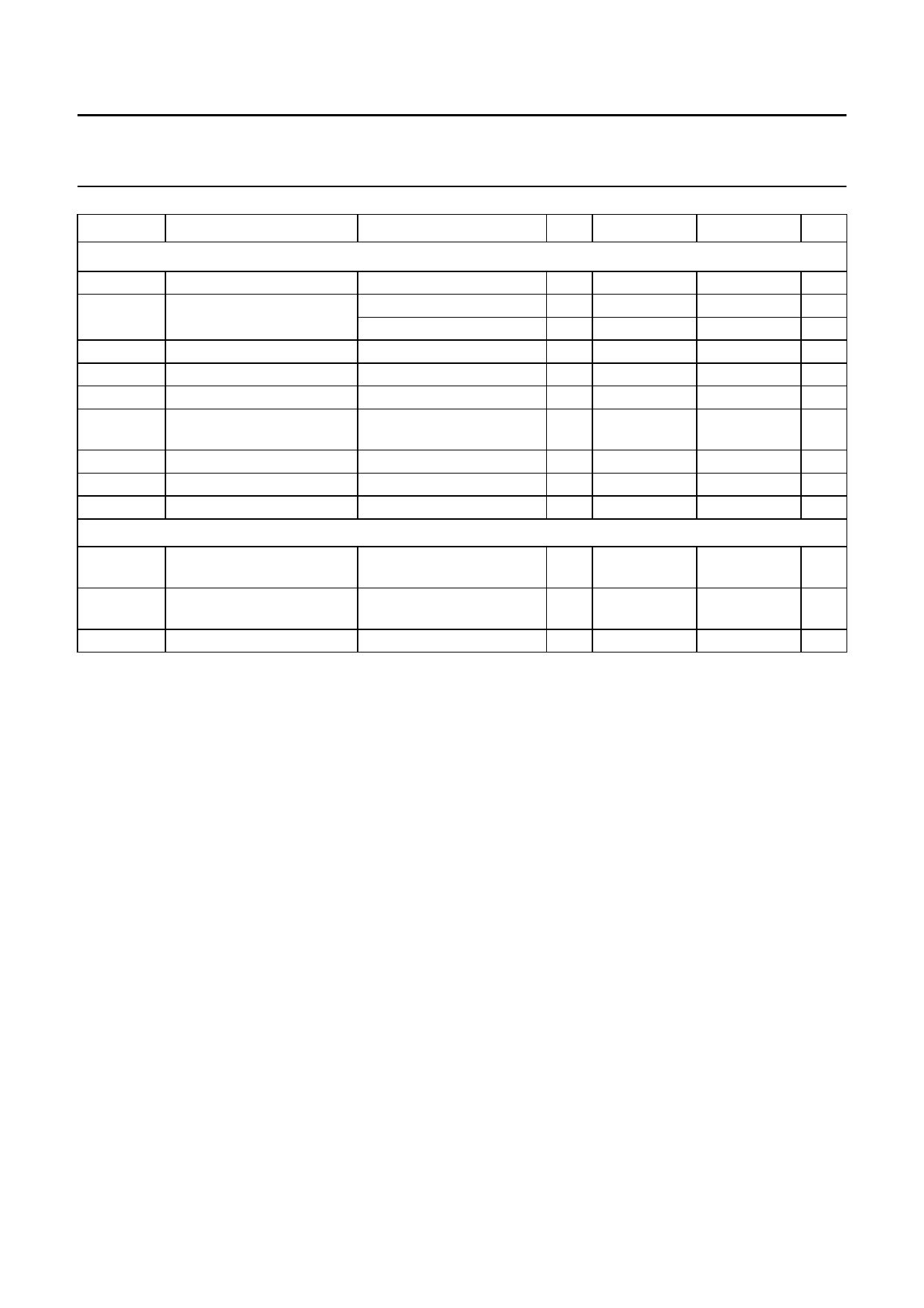
Philips Semiconductors
Multiple voltage regulator
Preliminary specification
TDA3617
SYMBOL
PARAMETER
CONDITIONS
MIN.
TYP.
MAX.
UNIT
Regulator 3 (IREG3 = 5 mA)
VREG3(off)
VREG3
output voltage off
output voltage
∆VREG3
∆VREGL3
IqREG3
SVRR3
line regulation
load regulation
quiescent current
supply voltage ripple
rejection
1 mA ≤ IREG3 ≤ 300 mA
5 V ≤ VP ≤ 17.5 V
5 V ≤ VP ≤ 17.5 V
1 mA ≤ IREG3 ≤ 300 mA
IREG3 = 300 mA
f = 3 kHz; Vi(p-p) = 2 V
−
1
3.14 3.3
3.14 3.3
−
2
−
20
−
10
60 70
400
mV
3.46
V
3.46
V
50
mV
50
mV
15
mA
−
dB
IREG3m
current limit
VREG3 > 3 V; note 4
0.35 0.45
−
A
IREG3sc
short circuit current
RL ≤ 0.5 Ω; note 5
15 50
−
mA
αct
cross talk noise
note 6
−
25
150
µV
Schmitt trigger for hold of regulator 3
Vthr
rising threshold voltage of VP rising
regulator 3
−
VREG1 − 0.15 VREG1 − 0.075 V
Vthf
falling threshold voltage of VP falling
regulator 2
2.7 VREG1 − 0.35 −
V
Vhys
hysteresis voltage
0.1 0.2
0.3
V
Notes
1. Minimum operating voltage, only if VP has exceeded 4.5 V.
2. The quiescent current is measured in the standby mode. Therefore, the enable inputs of regulators 1, 2 and 3 are
LOW (Ven < 1 V).
3. The drop-out voltage of regulators 1, 2 and 3 is measured between VP and VREGn.
4. At current limit, IREGmn is held constant (see Fig.5 for the behaviour of IREGmn).
5. The foldback current protection limits the dissipated power at short circuit (see Fig.5).
6. Perform the load regulation test with sine wave load of 10 kHz on the regulator output under test. Measure the RMS
ripple voltage on each of the remaining regulator outputs, using a 80 kHz low-pass filter.
1999 Jul 14
8
Share Link: 