MSM82C84A-2GS Ver la hoja de datos (PDF) - Oki Electric Industry
Número de pieza
componentes Descripción
Lista de partido
MSM82C84A-2GS Datasheet PDF : 18 Pages
| |||
¡ Semiconductor
MSM82C84A-2RS/GS/JS
(4) Ready Circuit
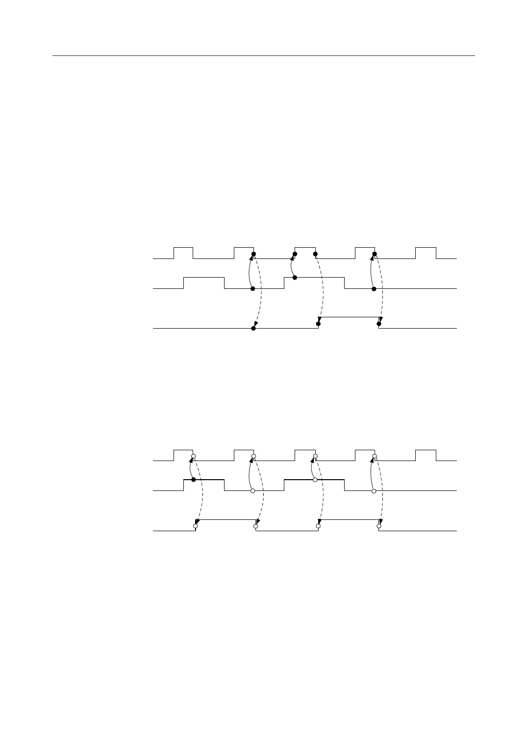
The READY signal generator circuit can be set to synchronization mode by ASYNC.
(i) When ASYNC is at low level
The RDY input is output as the READY signal by double synchronization.
The high-level RDY input is synchronized once by the rising edge of the CLK of the first
stage flip-flop (F1 in the circuit diagram), and then synchronized again by the falling
edge of the CLK of the next stage flip-flop (F2 in the circuit diagram), resulting in output
of a high-level READY output signal (see diagram below).
The low-level RDY input is synchronized directly by the falling-edge of the CLK of the
next stage flip-flop, resulting in output of a low-level READY output signal (see
diagram below).
CLK
RDY
READY
(ii) When ASYNC is at high level
The RDY input is output as the READY signal by single synchronization.
Both low-level and high-level RDY inputs are synchronized by the falling edge of the
CLK of the next stage flip-flop, resulting output of respective low-level and high-level
READY output signals (see diagram below).
CLK
RDY
READY
10/18
Share Link: 