W89C982 Ver la hoja de datos (PDF) - Winbond
Número de pieza
componentes Descripción
Lista de partido
W89C982 Datasheet PDF : 28 Pages
| |||
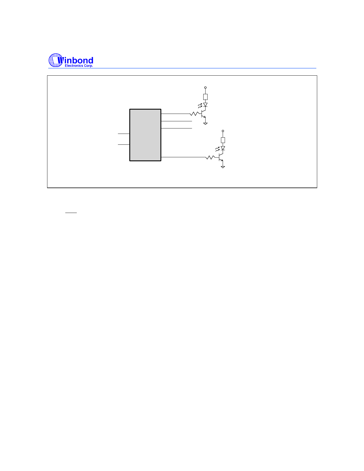
Preliminary W89C982AF
XCOLRPT
W89C982AF
AUIRPT
TP0RPT
M1
M0
.....
TP7RPT
* Set M1, M0 to select port status output.
R R = 330
Collision LED
....
R R = 330
TP7 status LED
Initial State After Reset
When RST is driven low, the IMPR II is reset. The minimum time the reset signal must be held low to
trigger a reset is 100 µS. During reset, the IMPR II places all outputs in the inactive state (except for
the auto polarity reversal function). Active low outputs stay high, active high outputs stay low, link test
is enabled, and the TP link is in a fail state. The AUI/TP auto partition/reconnection uses the standard
algorithm, AUI/TP transmitters are idle, AUI/TP receivers are enabled, IDAT and IJAM are in high-
impedance state, STR is low, and the auto polarity reversal function is enabled.
Management Logic and Management Interface
The major functions of the management logic are enabling/disabling networks, partitioning/recon-
necting network ports, enabling/disabling the link test and autopolarity reversal functions of the
twisted pair line transceiver, and accessing the link status and polarity status of the twisted pair line
transceiver. The management interface is a signal bus that contains input/output signals to/from the
management logic and the internal carrier sense signals for the nine network ports of the IMPR II.
The management logic can accept and execute management commands when the IMPR II is in
normal mode, i.e., the TEST pin of the IMPR II is tied low. All management commands are byte-
oriented and are clocked into the IMPR II serially by an external clock. Some of the commands
require an output from the IMPR II in response and some do not. At least 20 clocks are required to
send a command that requires an output response from the IMPR II; 14 clocks are needed to send a
command that requires no response. The serial command data stream and any associated output
response data stream are structured in a manner compatible with the RS232 serial data format, i.e.,
one start bit followed by eight data bits, with the LSB sent first and the MSB last.
- 11 -
Publication Release Date: November 1996
Revision A1
Share Link: 