CS8402A-IP Ver la hoja de datos (PDF) - Cirrus Logic
Número de pieza
componentes Descripción
Lista de partido
CS8402A-IP Datasheet PDF : 34 Pages
| |||
CS8401A CS8402A
SWITCHING CHARACTERISTICS - SERIAL PORTS
(TA = 25 °C for suffixes ’-CP’ and ’-CS’; TA = -40 to 85 °C for suffixes ’-IP’ and ’-IS’;
Inputs: Logic 0 = GND, logic 1 = VD+; CL = 20 pF)
Parameter
Symbol
Min
Typ
Max
Units
SCK Frequency
Master Mode
Slave Mode
Notes 5,6
Note 6
tsckf
IWR×64
12.5
Hz
MHz
SCK Pulse Width Low
Slave Mode
Note 6
tsckl
25
ns
SCK Pulse Width High
Slave Mode
Note 6 tsckh
25
ns
SCK rising to FSYNC edge delay
Notes 6,7 tsfds
20
ns
SCK rising to FSYNC edge setup
Notes 6,7
tsfs
20
ns
SDATA valid to SCK rising setup
Note 7
tsss
20
ns
SCK rising to SDATA hold time
Note 7
tssh
20
ns
C, U, V valid to SCK rising setup CS8402A
non-CD Mode
Notes, 7,8
tcss
0
ns
SCK rising to C, U, V hold time CS8402A
non-CD mode
Notes 7, 8
tscs
50
ns
U valid to SBC rising setup
CS8402A, CD mode Note 8
tuss
0
ns
SBC rising to U hold time
CS8402A, CD mode Note 8
tsuh
80
ns
RST Pulse Width
CS8402A
150
ns
Notes:
5. The input word rate, IWR, refers to the frequency at which stereo audio input samples are input to
the part. (A stereo pair is two audio samples.) Therefore, in Master mode, there are always
32 SCK periods in one audio sample.
6. Master mode is defined as SCK and FSYNC being outputs. In Slave mode they are inputs. In the
CS8401A, control reg. 3 bit 1, MSTR, selects master. In the CS8402A, only format 0 is master.
7. The table above assumes data is output on the falling edge and latched on the rising edge. In both
parts the edge is selectable. The table is defined for the CS8401A with control reg. 3 bit 0, SCED, set to
one, and for the CS8402A in formats 4 through 7. For the other formats, the table and figure edges
must be reversed (ie. "rising" to "falling" and vice versa).
8. The diagrams show SBC rising coincident with the first rising edge of SCK after FSYNC transitions.
This is true for all modes except FSF0 & 1 both equal 1 in the CS8401A, and format 4 in the CS8402A.
In these modes SBC is delayed one full SCK period.
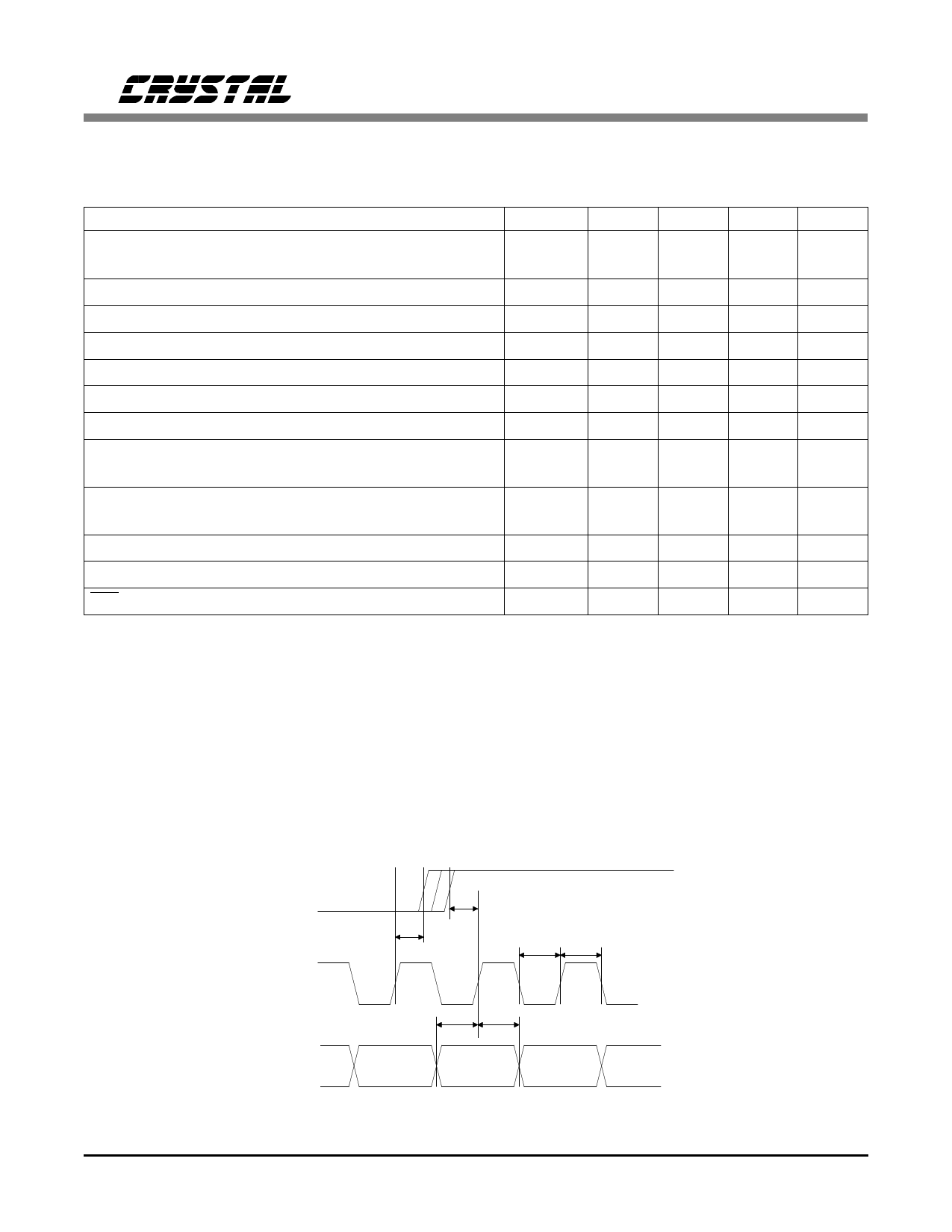
FSYNC
SCK
SDATA
t sfds
t sss
t sfs
t sckl t sckh
t ssh
Serial Input Timing - Slave Mode
4
DS60F1
Share Link: 