LX1660 Ver la hoja de datos (PDF) - Microsemi Corporation
Número de pieza
componentes Descripción
Lista de partido
LX1660 Datasheet PDF : 15 Pages
| |||
PRODUCT DATABOOK 1996/1997
LX1660/1661
ADVANCED PWM CONTROLLER
PRODUCTION DATA SHEET
T H E O R Y O F O P E R AT I O N
IC OPERATION
Referring to the block diagram and typical application circuit, the
output turns ON the top MOSFET, allowing the inductor current
to increase. At the error comparator threshold, the PWM latch is
reset, the top MOSFET turns OFF and the synchronous MOSFET
turns ON. The OFF-time capacitor CT is now allowed to discharge.
At the valley voltage, the synchronous MOSFET turns OFF and the
top MOSFET turns on. A special break-before-make circuit
prevents simultaneous conduction of the two MOSFETs.
To minimize frequency variation with varying output voltage,
the OFF-time is modulated as a function of the voltage at the OT
ADJ
pin. The OTADJ pin is also being monitored for a minimum voltage
of 0.7V. Below 0.7V the controller will shut down. A low voltage
at the EN pin or the OT pin will put the controller in a sleep
ADJ
mode. During the sleep mode the NINV pin is pulled low. This
discharges the external bypass capacitor on this pin and allows for
a soft-start.
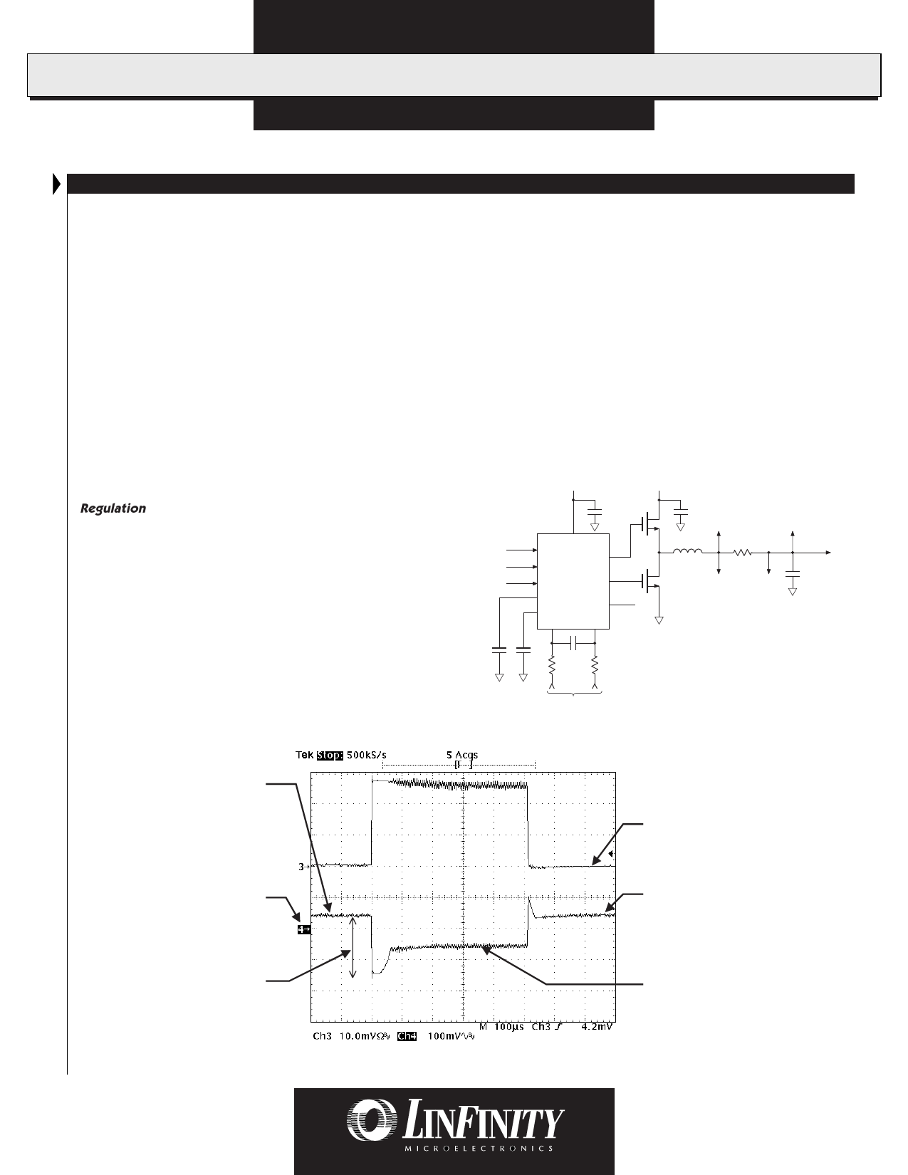
Regulation
LX1660 Only: The INV pin is connected to the negative side
of the sense resistor (i.e. the actual voltage supplied to the
load) — See Figure 2. The LX1660 will achieve a high DC set-
point accuracy, since it regulates at the load, but it will have
greater transient voltage over- and under-shoots than the LX1661.
LX1661 Only: The INV pin is connected to the positive side of
the sense resistor (between the inductor and the sense resistor)
— See Figure 2. The LX1661 has a 40mV offset to the NINV pin
to enhance transient response, as shown in Figure 3 below.
s The peak voltage at the V pin is 40mV higher than the set
FB
voltage and its average is the peak voltage minus the ripple volt-
age at V pin.
FB
s The output voltage is the voltage at the V pin minus the voltage
FB
drop across the current sensing resistor (I * RSENSE).
s At light loads, the voltage drop across the sensing resistor is small;
hence, the output voltage is approximately the voltage at the VFB
pin (approximately 40mV higher than the nominal set-point volt-
age, V ).
SET
s At heavy loads, larger current flows in the sense resistor, there-
fore, the voltage drop is higher and the output voltage is lower.
This adaptive positioning of the output voltage as the load
changes allows a greater output voltage excursion during a fast
step-load transient and requires fewer output capacitors to meet
the transient-response specification.
+VCC
+V
ENABLE
VFB
VCONTROL
C
Q1
EN
INV
NINV
A
TDRV
Q2
BDRV B
HICCUP
VREF
2V
CT
CS-
CS+
C
VFB
(LX1661)
L
RS
CS+
VFB
(LX1660)
COUT
CS-
LOAD
CHICCUP
CT
C
R
R
To RS
Figure 2 — LX1660 / 1661 General Circuit Configuration
Steady-state output voltage
at low current ~40mV
above nominal set-point
Load current
Nominal set-point
voltage, VSET
Voltage drop (mainly) due
to current change and ESR
of capacitors, ∆V = ∆I * ESR
(Effects of ESL ignored
in this analysis)
Figure 3 — Adaptive Voltage Positioning
Output voltage
(VOUT)
Steady-state voltage at
high current is approximately
VSET + 40mV - I * RSENSE
6
Copyright © 1998
Rev. 1.1 7/98
Share Link: 