IDT7027L(2018) Ver la hoja de datos (PDF) - Integrated Device Technology
Número de pieza
componentes Descripción
Lista de partido
IDT7027L Datasheet PDF : 20 Pages
| |||
IDT7027S/L
High-Speed 32K x 16 Dual-Port Static RAM
Industrial and Commercial Temperature Ranges
Description
The IDT7027 is a high-speed 32K x 16 Dual-Port Static RAM,
designed to be used as a stand-alone 512K-bit Dual-Port RAM or as a
combination MASTER/SLAVE Dual-Port RAM for 32-bit-or-more word
systems. Using the IDT MASTER/SLAVE Dual-Port RAM approach in 32-
bit or wider memory system applications results in full-speed, error-free
operation without the need for additional discrete logic.
The device provides two independent ports with separate control,
address, and I/O pins that permit independent, asynchronous access for
reads or writes to any location in memory. An automatic power down
feature controlled by the chip enables (CE0 and CE1) permits the on-chip
circuitry of each port to enter a very low standby power mode.
Fabricated using CMOS high-performance technology, these de-
vices typically operate on only 750mW of power. The IDT7027 is
packaged in a 100-pin Thin Quad Flatpack (TQFP) and a 108-pin ceramic
Pin Grid Array (PGA).
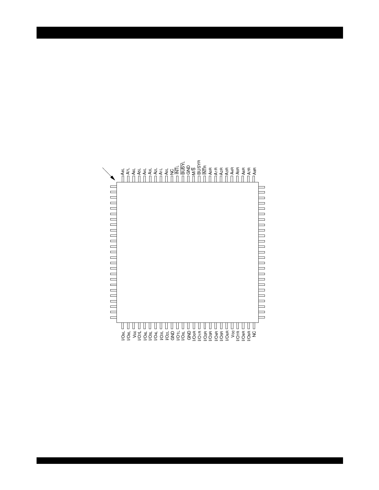
Pin Configurations(1,2,3)
INDEX
A9L
A10L
A11L
A12L
A13L
A14L
NC
NC
NC
LBL
UBL
CE0L
CE1L
SEML
Vcc
R/WL
OEL
GND
GND
I/O15L
I/O14L
I/O13L
I/O12L
I/O11L
I/O10L
1100 99 98
97 96 95
94
93 92
91 90
89 88
87 86
85 84
83 82
81
80 79
78 77
76
75
2
74
3
73
4
72
5
71
6
70
7
69
8
68
9
67
10
11
12
IDT7027PF
PN100(4)
66
65
64
13
100-Pin TQFP
63
14
Top View(5)
62
15
61
16
60
17
59
18
58
19
57
20
56
21
55
22
54
23
53
24
52
25
51
26 27 28 29 30 31 32 33 34 35 36 37 38 39 40 41 42 43 44 45 46 47 48 49 50
A9R
A10R
A11R
A12R
A13R
A14R
NC
NC
NC
LBR
UBR
CE0R
CE1R
SEMR
GND
R/WR
OER
GND
GND
I/O15R
I/O14R
I/O13R
I/O12R
I/O11R
I/O10R
3199 drw 02
NOTES:
1. All VCC pins must be connected to power supply.
2. All GND pins must be connected to ground supply.
3. Package body is approximately 14mm x 14mm x 1.4mm.
4. This package code is used to reference the package diagram.
5. This text does not indicate orientation of the actual part-marking.
6.242
Share Link: 