SMS44S Ver la hoja de datos (PDF) - Summit Microelectronics
Número de pieza
componentes Descripción
Lista de partido
SMS44S Datasheet PDF : 16 Pages
| |||
SMS44
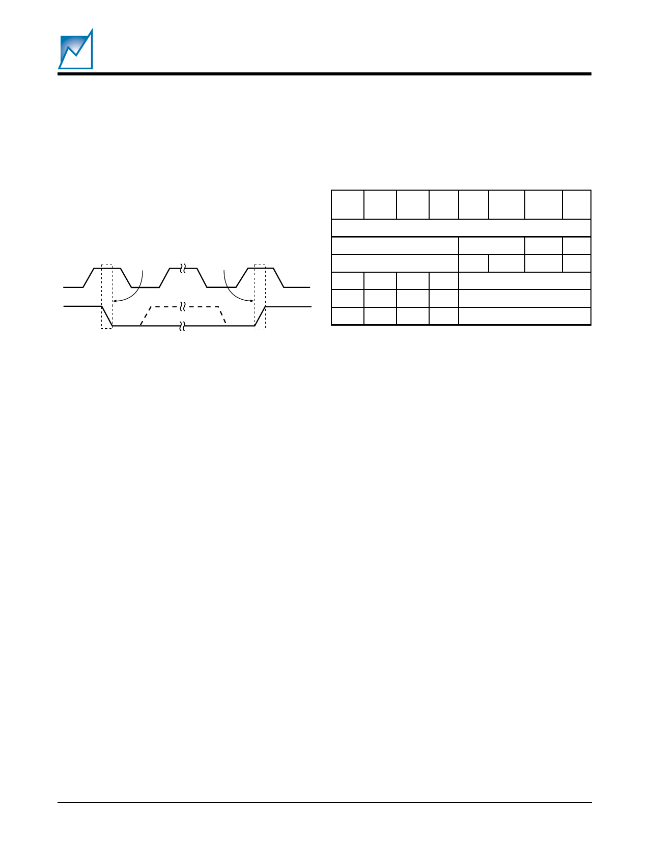
START and STOP Conditions
When both the data and clock lines are HIGH the bus is
said to be not busy. A High-to-Low transition on the data
line, while the clock is HIGH, is defined as the “START”
condition. A Low-to-High transition on the data line, while
the clock is HIGH, is defined as the “STOP” condition. See
Figure 9.
SCL
START
Condition
STOP
Condition
SDA In
2047 Fig09 1.0
Read/Write Bit
The last bit of the data stream defines the operation to be
performed. When set to “1” a read operation is selected;
when set to “0” a write operation is selected.
7
MSB
6
5 43
2
1
0
LSB
Address Bits
Device Type
Bus
MSB R/W
SMS44
x
x
x
x
1 0 0 1 Configuration Register
10
10
Memory (default)
10
11
Alternate Memory
2047 Table09 1.0
Table 9. Slave Addresses
Figure 9. START and STOP Conditions
WRITE OPERATIONS
Acknowledge (ACK)
Acknowledge is a software convention used to indicate
successful data transfers. The transmitting device, either
the master or the slave, will release the bus after transmit-
ting eight bits. During the ninth clock cycle the receiver will
pull the SDA line low to ACKnowledge that it received the
eight bits of data.
The SMS44 will respond with an ACKnowledge after
recognition of a START condition and its slave address
byte. If both the device and a write operation are selected
the SMS44 will respond with an ACKnowledge after the
receipt of each subsequent 8-bit word. In the READ mode
the SMS44 transmits eight bits of data, then releases the
SDA line, and monitors the line for an ACKnowledge
signal. If an ACKnowledge is detected and no STOP
condition is generated by the master, the SMS44 will
continue to transmit data. If an ACKnowledge is not
detected the SMS44 will terminate further data transmis-
sions and awaits a STOP condition before returning to the
standby power mode.
Device Addressing
Following a start condition the master must output the
address of the slave it is accessing. The most significant
four bits of the slave address are the device type identifier/
address. For the SMS44 the default is 1010BIN. The next
two bits are the Bus Address. The next bit (the 7th) is the
MSB of the memory address.
The SMS44 allows two types of write operations: byte
write and page write. A byte write operation writes a single
byte during the nonvolatile write period (tWR). The page
write operation, limited to the memory array, allows up to
16 bytes in the same page to be written during tWR.
Byte Write
After the slave address is sent (to identify the slave device
and select either a read or write operation), a second byte
is transmitted which contains the low order 8 bit address
of any one of the 512 words in the array. Upon receipt of
the word address the SMS44 responds with an ACKnowl-
edge. After receiving the next byte of data it again
responds with an ACKnowledge. The master then termi-
nates the transfer by generating a STOP condition, at
which time the SMS44 begins the internal write cycle.
While the internal write cycle is in progress the SMS44
inputs are disabled and the device will not respond to any
requests from the master.
Page Write (memory only)
The SMS44 is capable of a 16-byte page write operation.
It is initiated in the same manner as the byte-write opera-
tion, but instead of terminating the write cycle after the first
data word the master can transmit up to 15 more bytes of
data. After the receipt of each byte the SMS44 will respond
with an ACKnowledge.
The SMS44 automatically increments the address for
subsequent data words. After the receipt of each word, the
low order address bits are internally incremented by one.
2047 2.3 10/23/00
SUMMIT MICROELECTRONICS, Inc.
12
Share Link: 