IRG4BC20W(2004) Ver la hoja de datos (PDF) - International Rectifier
Número de pieza
componentes Descripción
Lista de partido
IRG4BC20W Datasheet PDF : 9 Pages
| |||
IRG4BC20WPbF
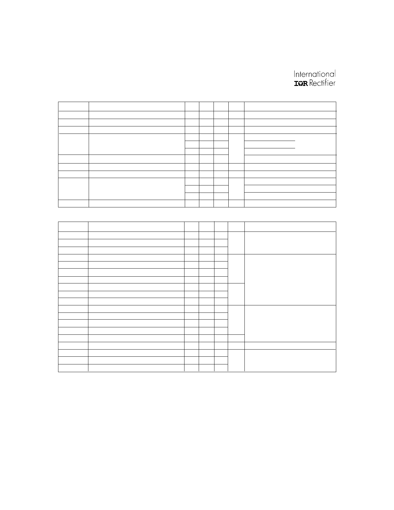
Electrical Characteristics @ TJ = 25°C (unless otherwise specified)
V(BR)CES
V(BR)ECS
∆V(BR)CES/∆TJ
VCE(ON)
VGE(th)
∆VGE(th)/∆TJ
gfe
ICES
IGES
Parameter
Collector-to-Emitter Breakdown Voltage
Emitter-to-Collector Breakdown Voltage
Temperature Coeff. of Breakdown Voltage
Collector-to-Emitter Saturation Voltage
Gate Threshold Voltage
Temperature Coeff. of Threshold Voltage
Forward Transconductance
Zero Gate Voltage Collector Current
Gate-to-Emitter Leakage Current
Min.
600
18
3.0
5.5
Typ.
0.48
2.16
2.55
2.05
-8.8
8.3
Max. Units
Conditions
V VGE = 0V, IC = 250µA
V VGE = 0V, IC = 1.0A
V/°C VGE = 0V, IC = 1.0mA
2.6
IC = 6.5A
VGE = 15V
V
IC = 13A
See Fig.2, 5
IC = 6.5A , TJ = 150°C
6.0
VCE = VGE, IC = 250µA
mV/°C VCE = VGE, IC = 250µA
S VCE = 100 V, IC = 6.5A
250 µA VGE = 0V, VCE = 600V
2.0
VGE = 0V, VCE = 10V, TJ = 25°C
1000
VGE = 0V, VCE = 600V, TJ = 150°C
±100 nA VGE = ±20V
Switching Characteristics @ TJ = 25°C (unless otherwise specified)
Qg
Qge
Qgc
td(on)
tr
td(off)
tf
Eon
Eoff
Ets
td(on)
tr
td(off)
tf
Ets
LE
Cies
Coes
Cres
Notes:
Parameter
Total Gate Charge (turn-on)
Gate - Emitter Charge (turn-on)
Gate - Collector Charge (turn-on)
Turn-On Delay Time
Rise Time
Turn-Off Delay Time
Fall Time
Turn-On Switching Loss
Turn-Off Switching Loss
Total Switching Loss
Turn-On Delay Time
Rise Time
Turn-Off Delay Time
Fall Time
Total Switching Loss
Internal Emitter Inductance
Input Capacitance
Output Capacitance
Reverse Transfer Capacitance
Min.
Typ.
26
3.7
10
22
14
110
64
0.06
0.08
0.14
21
15
150
150
0.34
7.5
490
38
8.8
Max.
38
5.5
15
160
96
0.2
Units
nC
ns
mJ
ns
mJ
nH
pF
Conditions
IC = 6.5A
VCC = 400V
See Fig.8
VGE = 15V
TJ = 25°C
IC = 6.5A, VCC = 480V
VGE = 15V, RG = 50Ω
Energy losses include "tail"
See Fig. 9, 10, 14
TJ = 150°C,
IC = 6.5A, VCC = 480V
VGE = 15V, RG = 50Ω
Energy losses include "tail"
See Fig. 10, 11, 14
Measured 5mm from package
VGE = 0V
VCC = 30V
See Fig. 7
= 1.0MHz
Repetitive rating; VGE = 20V, pulse width limited by
max. junction temperature. ( See fig. 13b )
VCC = 80%(VCES), VGE = 20V, L = 10µH, RG = 50Ω,
(See fig. 13a)
Repetitive rating; pulse width limited by maximum
junction temperature.
Pulse width ≤ 80µs; duty factor ≤ 0.1%.
Pulse width 5.0µs, single shot.
2
www.irf.com
Share Link: 